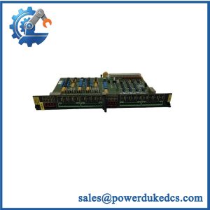
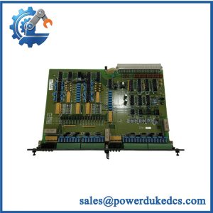
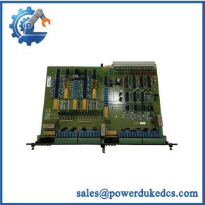
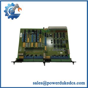
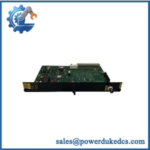
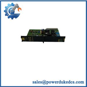
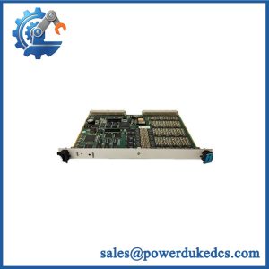
Description
-
Brand: DEIF
-
Full Model Number: PSM-1
-
Product Family: Delomatic-3 Multi-Function Generator Control System
-
Documented Part Reference: 4921240048D; verify the actual nameplate before ordering
-
Lifecycle Status: Legacy product; current OEM lifecycle classification and spare-part availability require confirmation
-
Core Function: DC power supply for modules installed in the Delomatic-3 Generator Unit (DGU)
-
Top 3 Technical Specs: Nominal 24 V DC input; backplane outputs of ±5 V DC, ±12 V DC, and ±15 V DC; typical power consumption of 10 W with a maximum of 15 W for the PSM-1 itself
-
Input Tolerance: +30% / -25%; input voltage must never exceed 32 V DC
-
Protection: Internal protection against voltage surges and transients; galvanic isolation between the source supply and the Delomatic system
-
Dimensions and Weight: 40.7 mm wide (8 TE); 0.45 kg
-
Stock & Condition: Actual quantity, physical condition, revision, test status, and dispatch date require confirmation
Obsolescence & Supply Chain Assessment
A failed DEIF PSM-1 can disable multiple modules within a Delomatic-3 generator control cabinet. This power supply module generates the backplane voltages required by the installed DGU modules, rather than controlling generator operation directly. When sourcing a replacement, verify the PSM-1 designation, the associated part reference, and the existing rack configuration. The original DEIF documentation also warns that short-term power loss must be avoided because it may damage the module. Procurement planning should therefore address both replacement availability and the maintenance procedure required for a safe changeover.
Replacing a confirmed faulty PSM-1 may avoid the expense of replacing an otherwise serviceable Delomatic-3 control system. The total cost of ownership (TCO) calculation should include the spare module, maintenance labor, electrical verification, restoration checks, and generator downtime. For preliminary budgeting, allow approximately 1–2 maintenance labor hours for a straightforward replacement and basic operational verification, excluding fault diagnosis and extended commissioning. This is a planning estimate, not a guaranteed completion time. Before purchasing surplus stock, request actual-unit photographs, identification details, a written condition declaration, and the agreed electrical test report. If multiple DGU modules show power-related faults, investigate the incoming supply and total backplane load before attributing every failure to the PSM-1.
Compatibility & Replacement Matrix
|
Replacement Scenario |
Classification |
Required Action |
Preliminary Time Allowance |
|---|---|---|---|
|
Exact DEIF with matching identification and approved configuration |
Conditional drop-in replacement |
Verify part identification, rack compatibility, supply wiring, and installed-module requirements. Follow the OEM replacement procedure. |
1–2 maintenance labor hours |
|
with different hardware identification or revision |
Engineering verification required |
Compare the nameplate, applicable documentation, mechanical fit, electrical characteristics, and rack requirements. |
1–2 engineering hours for initial review |
|
PSM-2 or another power supply proposed as an alternative |
Not an automatic replacement |
Verify output rails, current capacity, terminal assignment, mounting, isolation, and system approval before substitution. |
Estimate after technical review |
|
Replacement involving wiring or rack modifications |
Potential hardware modification |
Review electrical drawings, backplane requirements, protection arrangements, and commissioning procedures. |
Site-specific estimate required |
Cost planning: Calculate the installed replacement cost using the quoted module price, maintenance labor, required testing, and downtime exposure. A non-equivalent supply may introduce additional engineering and configuration costs. Do not assume that equal input voltage or a similar physical size establishes interchangeability.
Field Traps to Check Before Ordering
-
Input voltage limits: The nominal supply is 24 V DC, with a specified tolerance of +30% / -25%. The input must never exceed 32 V DC. Verify the actual voltage at the supply terminals before energizing the replacement.
-
Power interruption risk: DEIF explicitly warns against short-term power loss because it may damage the module. Arrange the replacement sequence and control-system shutdown in accordance with the applicable OEM instructions.
-
Backplane loading: The supplies ±5 V DC, ±12 V DC, and ±15 V DC rails. Total power demand depends on the modules installed in the rack. Confirm the intended rack configuration and power requirements rather than considering only the ‘s own consumption.
-
External fuse: The documented maximum external fuse rating is 6 A, slow-blow. Verify the specified protection arrangement and actual installation drawings before reconnecting the unit.
-
Low-power indication: A red LOW POWER indicator identifies insufficient supply capability under the documented conditions. Investigate the input supply and module load before concluding that the replacement module is defective.
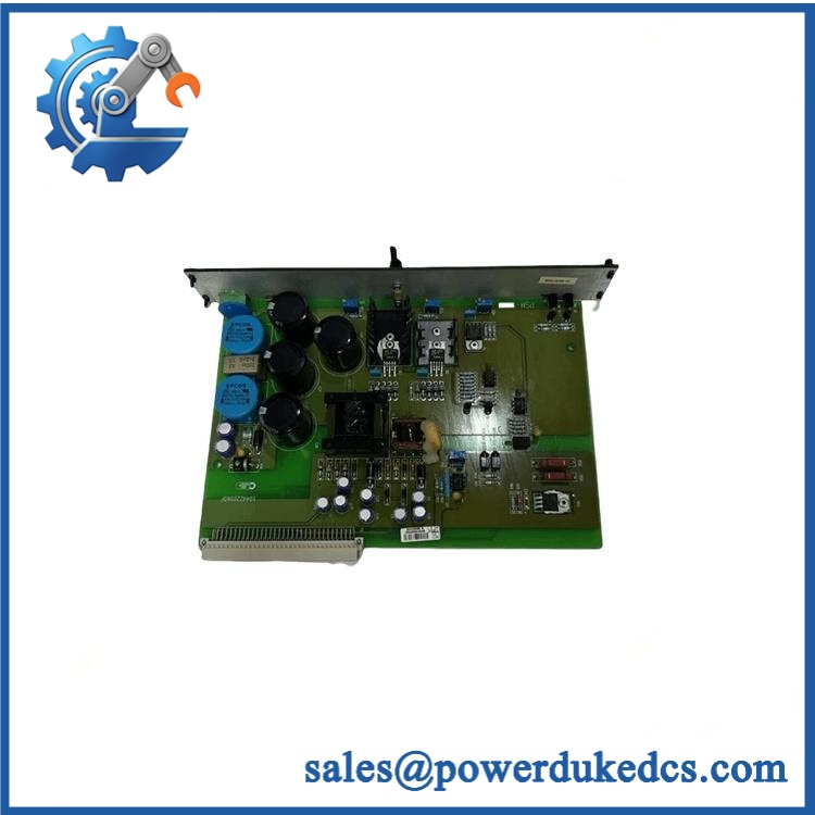
DEIF PSM-1
Quality Assurance & Testing SOP
The following procedure defines the proposed pre-shipment acceptance scope for DEIF inventory. The exact test setup must be suitable for the Delomatic-3 power supply and its specified backplane outputs.
Visual Inspection and Traceability
-
Part-number verification: Match the designation and available part reference against the purchase specification.
-
Physical inspection: Examine the enclosure, terminal blocks, connectors, and accessible surfaces for corrosion, contamination, impact damage, and signs of unauthorized repair.
-
Authenticity screening: Inspect manufacturer markings, label consistency, assembly identification, and available traceability records.
-
Condition documentation: Record whether the unit is new original, new surplus, or previously used, as applicable.
-
Photographic evidence: Capture the actual module, identification label, front panel, and supply terminals before packaging.
Power-On and Electrical Checks
-
Verify the test supply polarity and nominal 24 V DC input before energization.
-
Use a controlled test setup with suitable protection and monitoring equipment.
-
Avoid short-term supply interruptions and repeated rapid power cycling, consistent with the OEM warning.
-
Check the green POWER OK indicator and red LOW POWER indicator against the documented operating conditions.
-
Measure the ±5 V DC, ±12 V DC, and ±15 V DC backplane outputs with suitable calibrated instruments.
-
Verify that input voltage remains within the specified limits throughout the test.
-
Record the input voltage, measured output rails, indicator states, and any abnormal behavior.
Load and Isolation Testing
-
Test the module in a compatible Delomatic-3 rack or an approved test fixture where available.
-
Verify stable backplane supply under an appropriate representative load, accounting for the installed-module configuration.
-
Check for unexplained voltage deviation, intermittent behavior, or low-power indications.
-
Verify the galvanic isolation requirement only through a suitable, approved test procedure that will not damage the electronics.
-
Confirm the external fuse specification and terminal condition against the applicable documentation.
-
Record all measured values and test conditions. Do not claim full-load or isolation-test compliance if the corresponding test was not performed.
Final Acceptance and Shipment Release
-
Match the tested unit’s identification details to the sales documentation.
-
Provide actual-unit photographs and the agreed inspection and electrical-test records.
-
Disclose any tests not performed and any limits of the test fixture.
-
Package the module with suitable mechanical protection and handling precautions.
-
Release the module only when the agreed acceptance requirements have been satisfied.
Testing limitation: A bench-tested does not establish the condition of every module powered by the DGU. After replacement, qualified personnel must verify the incoming supply, backplane voltages, relevant module status indicators, and the required system functions before returning the generator control system to service.
Procurement & Lifecycle FAQ
Is the DEIF in stock, and what is the emergency shipping cutoff?
Availability must be confirmed against physical inventory for the exact and applicable part reference. Request the quantity, condition, identification details, test status, warehouse location, and confirmed dispatch date. Emergency shipping depends on payment clearance, export documentation, packaging, and carrier collection times. Same-day dispatch requires written confirmation.
How do you verify the authenticity and condition of a ?
Request photographs of the actual module, identification label, terminals, and visible condition. Ask for available traceability records and a written condition declaration. For units sold as tested, specify the required input-voltage and backplane-output measurements and request the corresponding report. Visual inspection alone cannot establish electrical performance.
Are firmware or configuration changes required when replacing the ?
The DEIF replacement instruction states that no DIP-switch settings or other settings are required. For an exact replacement, firmware changes are not indicated by that instruction. Confirm the installed Delomatic-3 configuration and applicable replacement procedure before installation; do not assume another power supply uses the same connections or electrical characteristics.
What warranty and return terms should be agreed before purchasing?
Confirm the warranty duration, start date, defect coverage, exclusions, return authorization process, and deadline for reporting a defective-on-arrival unit. Establish the required supporting evidence and responsibility for return freight. Record these terms in the quotation or purchase order, particularly for surplus or previously used inventory.
Can the DEIF be replaced by a generic 24 V DC power supply?
Not without an engineering review. The provides several regulated positive and negative backplane voltage rails and galvanic isolation between the source supply and the Delomatic system. A generic supply that provides only 24 V DC does not automatically provide these functions. Verify the output rails, load capacity, isolation requirements, mounting, terminal arrangement, and system approval before considering an alternative.