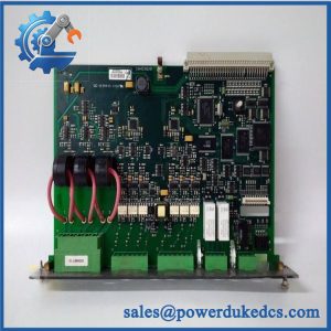
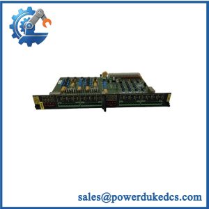
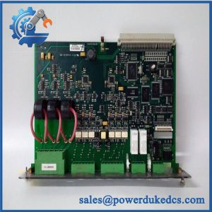
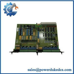
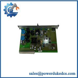
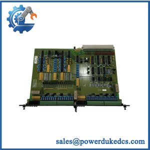
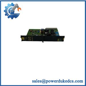
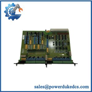
Description
-
Brand: DEIF
-
Full Model Number: SCM-2 1044220110E
-
Product Type: Synchronizing and Measuring Module
-
System Platform: DEIF DELOMATIC-3 Multifunction Power Management System
-
Lifecycle Status: Legacy platform; current manufacturing and support status require confirmation
-
Core Function: Three-phase electrical measurement, generator synchronization, breaker control, and associated protection functions
-
Top 3 Technical Specifications:
-
Voltage Measurement: Selectable 100–200 VAC, 201–379 VAC, or 380–690 VAC phase-to-phase ranges, with ±20% range tolerance
-
Current Measurement: Three-phase current input for 1 A or 5 A current transformer secondaries; typical internal burden of 0.3 VA per phase
-
Synchronization: ±5 electrical degrees accuracy; 45–65 Hz operating frequency range
-
-
Breaker Control Outputs: Two potential-free relay outputs; AC rating up to 250 V, 5 A, 1,000 VA; DC rating up to 250 V, 1 A, 50 W
-
Breaker Feedback: Potential-free binary input contacts
-
Measurement Performance: Class 1 accuracy according to IEC 688 under specified reference conditions
-
Power Supply: Supplied from the DELOMATIC power supply module through the backplane
-
Power Consumption: Typically 2 W; maximum 3 W
-
Dimensions: 12 TE module width; 60.96 mm
-
Weight: Approximately 0.85 kg
-
Stock and Condition: Physical availability, hardware revision, EEPROM identification, and condition subject to confirmation
-
Dispatch Lead Time: Confirmed after stock verification and order approval
-
Warranty: Written warranty terms required before purchase order approval
Obsolescence and Supply Chain Deep Dive
A synchronizing-module failure can prevent a generator breaker from closing under the required electrical conditions, delaying restoration of parallel operation or power distribution. The DEIF SCM-2 1044220110E combines three-phase measurement, synchronization, and generator-breaker control within the DELOMATIC-3 system. It measures generator and busbar electrical parameters, communicates measurement results to the control module, and coordinates breaker commands with the application program. For maintenance teams supporting existing marine or industrial power installations, the primary procurement risk is obtaining the correct hardware and configuration. A matching SCM-2 designation is not sufficient unless the voltage-range jumpers, I/O address, and EEPROM identification also meet the original system requirements.
For an established DELOMATIC-3 installation, a verified replacement may cost considerably less than migrating the complete power-management system. Total Cost of Ownership (TCO) should include the spare module, freight, qualified labor, electrical configuration checks, commissioning, and the financial exposure associated with an extended outage. Retaining the existing architecture can limit immediate engineering and switchboard modification costs, provided the replacement is technically approved. However, legacy inventory does not guarantee future availability. Record the installed module configuration, retain the original application documentation, and evaluate an approved migration path if sourcing times increase or recurring failures raise lifecycle costs (availability and delivery schedules depend on the actual stock lot and its condition).
Compatibility and Replacement Matrix
The SCM-2 is a synchronizing and measuring module, not a generic generator controller. DEIF’s replacement instructions identify separate SCM-B and SCM-C circuit boards, with distinct configuration requirements. Confirm these details before approving the replacement.
|
Replacement Scenario |
Compatibility Assessment |
Required Action |
|---|---|---|
|
SCM-2 1044220110E with matching hardware and configuration |
Candidate drop-in replacement |
Verify the complete part number, ordering number, version, EEPROM identification, and installed system |
|
SCM-2 with different EEPROM or application identification |
Compatibility requires verification |
Match the ordering number, version number, item number, and required module ID |
|
with different voltage-measurement configuration |
Reconfiguration required where applicable |
Verify the generator and busbar voltage ranges and corresponding PCB jumper settings |
|
installed with a duplicate rack I/O address |
Configuration conflict |
Assign a unique I/O address under the applicable DELOMATIC configuration |
|
SCM-1 or another synchronization module proposed as a substitute |
Not an established drop-in replacement |
Obtain manufacturer-approved interchangeability or migration instructions |
|
Replacement involving wiring, rack, or measurement-circuit changes |
Hardware modification may be required |
Complete engineering review and approve changes before installation |
Replacement Cost and Time Estimates
These are preliminary maintenance-planning allowances, not DEIF-approved service durations or supplier quotations.
|
Activity |
Preliminary Planning Allowance |
|---|---|
|
Part identification and compatibility review |
30–60 minutes |
|
EEPROM and I/O address verification |
30–60 minutes |
|
Voltage-range jumper inspection |
30–60 minutes |
|
Like-for-like removal and installation |
1–2 labor hours |
|
Synchronization and breaker-control testing |
2–4 labor hours |
|
Replacement module and expedited freight |
Supplier quotation required |
|
Preliminary maintenance window |
Approximately 3–6 hours, subject to site conditions |
The estimated maintenance window assumes that documentation is available and no wiring changes are necessary. It excludes extensive troubleshooting, switchboard access delays, and repairs to connected equipment. Generator synchronization and breaker-control commissioning may require additional time under the site’s approved test procedures.
Field Traps to Check Before Ordering
EEPROM identification mismatch: The DEIF replacement instructions specify that the replacement unit must receive the same ID number as the unit being replaced. They also require matching EEPROM ordering numbers, version numbers, and item numbers. Verify these identifiers before installation; identical external markings alone do not confirm application compatibility.
I/O address and voltage-range jumpers: The SCM-B board uses switch S2 to set the backplane I/O address. SCM-1, , and PRM-1 modules in the rack must use distinct addresses within the documented address range. On the SCM-C board, jumpers determine the generator and busbar voltage-measurement ranges. Check both sets of settings against the original configuration.
Electrical input limits: The documented maximum direct AC measurement voltage is 690 VAC. Higher system voltages require suitable voltage-measuring transformers. Confirm the installation’s phase-to-phase voltage, current transformer secondary rating, external fuse arrangement, and measurement-range settings before applying power.
Never assume that energized replacement is permitted. Follow the applicable DELOMATIC instructions, site isolation procedures, and approved electrical safety requirements.
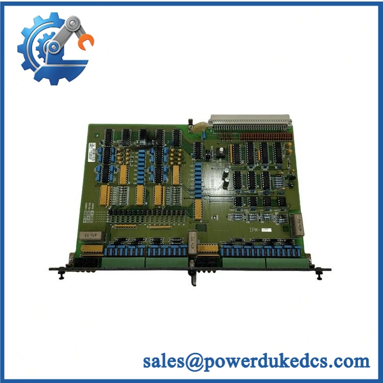
DEIF SCM-2 1044220110E
Quality Assurance and Testing SOP
Pre-shipment QA for the DEIF 1044220110E should establish the identity, physical condition, configuration, and functional response of the actual unit offered. Because the module participates in generator synchronization and breaker control, testing must address measurement inputs and control outputs rather than relying on a basic power-on check.
|
QA Stage |
Required Procedure |
Acceptance Criteria |
|---|---|---|
|
Part identification |
Record 1044220110E markings, available serial information, ordering number, version, and item number |
Identity matches the purchase specification |
|
OEM anti-counterfeit visual inspection |
Examine labels, PCB markings where accessible, component condition, soldering, connectors, and evidence of unauthorized repair |
No unexplained identification discrepancies or physical defects affecting use |
|
Mechanical inspection |
Inspect the 12 TE module, terminal connections, PCB assembly, and mating interfaces |
No damage, corrosion, or connector defects affecting installation |
|
EEPROM verification |
Record EEPROM identifiers and compare them with the required system configuration |
Required ordering and version information confirmed |
|
Power-on self-test (POST) |
Power the module through a compatible DELOMATIC rack or approved test arrangement |
Startup behavior agrees with the applicable technical instructions |
|
Status indicator verification |
Record the actual fitted indicators; inspect ERR/RUN LEDs only where present |
Indicator states documented without assuming generic LED labels |
|
Voltage measurement test |
Apply suitable calibrated test signals to the documented measurement inputs and verify the configured range |
Measured values meet the applicable acceptance criteria |
|
Current measurement test |
Verify the configured 1 A or 5 A current-transformer input using appropriate test equipment |
Measurement response matches the selected configuration |
|
Synchronization test |
Simulate or verify frequency, voltage, and phase-angle conditions on both sides of the controlled breaker |
Synchronization decisions agree with the documented settings and test procedure |
|
Breaker-control relay test |
Exercise both potential-free relay outputs under suitable controlled test conditions |
Relay switching and contact behavior meet the agreed test criteria |
|
Breaker feedback test |
Verify the potential-free feedback input using an approved test arrangement |
Feedback transitions are detected as expected |
|
Final inspection and packing |
Photograph the actual unit, record test results, and use suitable ESD-protective packaging |
Shipped module matches the inspected unit and its test record |
Pre-Shipment Test Report
The test report should identify the unit, inspection date, hardware and EEPROM markings, test equipment where applicable, measurement ranges, relay tests, and any limitations.
A power-on test does not establish accurate electrical measurement or correct synchronization behavior. Successful relay switching alone does not prove that the complete generator-control application is configured correctly. Full-system acceptance requires a suitable test environment and qualified personnel.
Where a complete DELOMATIC test rack is unavailable, document the limitation in writing. Do not represent untested synchronization or breaker-control functions as fully verified. Extended monitored testing should be claimed only when supported by recorded results.
Procurement and Lifecycle FAQ
Is the DEIF 1044220110E genuinely in stock, and what is the emergency shipping cutoff?
Physical inventory must be confirmed for the exact part number and configuration. Request written confirmation of quantity, condition, module markings, test coverage, and expected dispatch date. Emergency shipping depends on order approval, payment clearance, packing requirements, export documentation, and carrier collection. No fixed dispatch cutoff should be assumed without confirmation.
How do you verify the condition and authenticity of an obsolete or surplus ?
Request photographs of the actual module, identification markings, PCB condition, and available EEPROM information. The quotation should distinguish new original, new surplus, and used equipment, as applicable. Ask for available traceability records and a unit-specific inspection report. Visual inspection alone cannot establish authenticity or complete functional performance.
Are there firmware or configuration compatibility issues to resolve before issuing the purchase order?
Yes. Confirm the EEPROM ordering number, version number, item number, and required module ID. Verify the rack I/O address and the voltage-range jumpers on the SCM-B and SCM-C boards. Check the configured voltage and current measurement ranges against the existing installation. Do not assume that a matching model designation guarantees an identical application configuration.
What warranty and return terms apply to the DEIF ?
The written quotation should specify the warranty period, coverage, defective-on-arrival procedure, return authorization requirements, and exclusions. For surplus or used modules, confirm whether the warranty covers functional failure and what evidence is required for a claim. Retain the identification photographs, test report, packing records, and shipping documents.
Is replacing the more economical than upgrading the DELOMATIC-3 system?
A verified like-for-like replacement may have a lower immediate cost when the existing power-management installation remains suitable. Compare the module price, expedited freight, qualified labor, configuration checks, synchronization testing, and downtime exposure against the cost of a new control platform, engineering changes, installation, and validation. If spare availability is uncertain, incorporate future inventory requirements and a planned system migration into the lifecycle assessment.