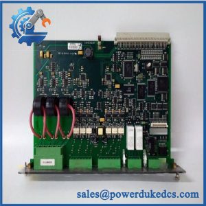
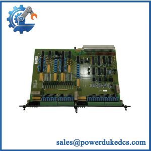
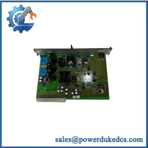
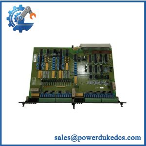
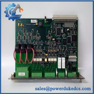
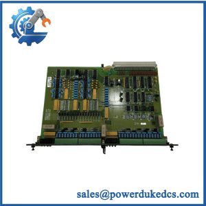
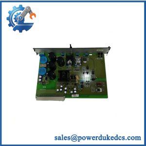
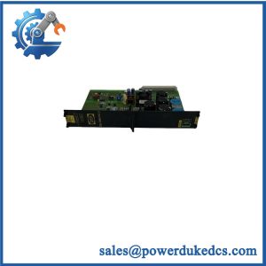
Description
- Brand: DEIF
- Full Model Number: PCM4.4
- Lifecycle Status: Legacy Delomatic 400 platform; current part-level lifecycle and supply status require confirmation
- Core Function: Distributed I/O and fieldbus controller for a Delomatic 400 extension rack
- System Role: Controls an extension rack when the main rack lacks sufficient capacity; communicates with the main PCM module via ARCNET
- Top 3 Technical Specs: 18–36 VDC power input, maximum 6 A; 3 independent CAN bus lines at 125/250 kbps; 1 ARCNET interface supporting electrical or optical connection
- Additional Interfaces: 1 RS422/485 port at 9,600–57,600 baud; 1 TTL display port at 4,800–57,600 baud; USB service interface at 256,000 baud
- Relay Output: Normally open; rated 250 VAC or 24 VDC, 8 A
- Digital Input: Potential-free contact input; open/close sensing at 5 V / 7.5 mA
- Memory: 2 MB RAM; 32 KB non-volatile RAM; 1 MB flash
- Module Width: 8 TE (40.64 mm)
- Stock & Condition: Confirm physical availability, condition, hardware revision, test records, and dispatch lead time before purchase
Technical specifications above follow DEIF’s published Delomatic 400 Gas datasheet for the PCM 4.4 module. Verify the installed system variant and actual unit markings before ordering.
Obsolescence & Supply Chain Deep Dive
When a Delomatic 400 extension rack loses its controller, replacement sourcing can delay the return of the associated control and monitoring functions. The DEIF PCM4.4 is a distributed I/O and fieldbus controller intended for an extension rack rather than the main rack’s PCM4.3 controller. The two modules communicate through ARCNET. That distinction matters during procurement: a PCM4.4 should not be selected as a substitute for a failed PCM4.3 merely because both modules belong to the same system family. Confirm the original module designation, rack position, communication arrangement, and application documentation before releasing the purchase order.
For an installed control system with serviceable field wiring and application software, replacing a failed PCM4.4 may cost less than migrating the entire control platform. The total cost of ownership (TCO) comparison should include the replacement module, freight, technician labor, configuration checks, commissioning, and downtime risk. A wider migration may also require controller engineering, I/O reassignment, wiring changes, application validation, and a planned outage. A verified legacy spare can help contain those immediate costs, although future availability of compatible modules remains a lifecycle risk. (For urgent sourcing, physical stock and completed test evidence should be confirmed before payment or dispatch commitments.)
Compatibility & Replacement Matrix
| Evaluation Item | Engineering and Procurement Guidance |
|---|---|
| Replacement classification | Conditional drop-in replacement for a matching .4 configuration |
| Rack compatibility | Confirm Delomatic 400 rack type, module position, backplane connections, and supported system variant |
| Controller compatibility | Verify that the installed main PCM module and application configuration support the replacement |
| Software compatibility | Preserve the existing configuration records; verify controller parameters and extension-rack assignments |
| Firmware requirements | No firmware flash should be assumed necessary. Confirm the approved software and hardware combination before installation |
| Hardware modification | Normally unnecessary for a verified like-for-like replacement; verify mounting, connector alignment, and rack wiring |
| Power supply | 18–36 VDC, maximum 6 A per the published module specification |
| ARCNET communication | Check the communication medium, port arrangement, connection integrity, and communication parameters |
| Estimated replacement time | Approximately 2–4 technician-hours for a straightforward exchange and initial operational checks; additional commissioning may extend this period |
| Cost estimate | Module price + freight + 2–4 technician-hours at the local labor rate + any required commissioning or shutdown costs |
| Acceptance requirement | Confirm startup diagnostics, ARCNET communication, fieldbus connections, relay output, digital input, and controller recognition |
Field Traps to Check Before Ordering
.4 versus .3 identification
The .4 serves as an extension-rack controller, while the .3 is specified as the main power and control module. They have different system roles and interface arrangements. Check the original label, rack position, and wiring documentation before ordering. Do not approve a substitution based only on the shared PCM designation.
ARCNET and communication configuration
The .4 communicates with the main PCM through ARCNET. Its documented interface supports electrical or optical connection, depending on the configuration. Verify the installed connection type, cable or fiber arrangement, port settings, and communication parameters. A physically compatible module may still fail to communicate if the existing configuration is incorrect or incompatible.
Quality Assurance & Testing SOP
A replacement .4 should be inspected and tested using a compatible Delomatic 400 setup. Testing must confirm the module’s identity and physical condition before proceeding to electrical and communication checks. Do not treat successful power-up as proof of full operational capability.
| QA Stage | Required Action | Acceptance Evidence |
|---|---|---|
| Identification | Record DEIF branding, .4 designation, available serial or lot identifiers, and PCB revision markings | Identification photographs and inspection record |
| OEM anti-counterfeit visual inspection | Inspect labels, PCB markings, connectors, component placement, solder joints, and signs of unauthorized rework | Recorded inspection findings; discrepancies investigated |
| Physical inspection | Check the casing, mounting edges, terminals, connectors, and visible components for corrosion, damage, or contamination | Condition report and photographs |
| Power-on test | Supply the specified 18–36 VDC through a compatible test arrangement, observing applicable current limits | Recorded supply voltage, current observations, and startup results |
| Startup diagnostics | Review available controller diagnostics and module status indicators, including ERR/RUN LEDs only where fitted and documented | Recorded diagnostic states and fault indications |
| ARCNET communication | Connect to a compatible main PCM or approved test setup and verify the extension-rack communication link | Communication status and recorded test results |
| CAN interface testing | Exercise the three CAN interfaces with suitable equipment at supported bus rates | Port-level communication results |
| RS422/485 and display interface checks | Verify the applicable serial interface and TTL display connection using compatible test equipment | Recorded interface responses |
| Digital input testing | Operate the potential-free contact input using an approved test arrangement | Verified open/close state changes |
| Relay output testing | Exercise the normally open relay output under controlled conditions and within its rated electrical limits | Contact operation and measured test conditions |
| Service interface check | Verify the USB service interface where suitable authorized service equipment is available | Recorded connection result |
| Final inspection | Recheck connector condition, module identification, packing protection, and test documentation | Completed QA record and shipment inspection |
QA release criteria: A unit should not be described as fully tested unless the claimed tests were completed and documented. If only visual inspection and power-on checks are available, disclose that limited coverage. Communication and load testing require compatible equipment, approved procedures, and appropriate acceptance criteria.
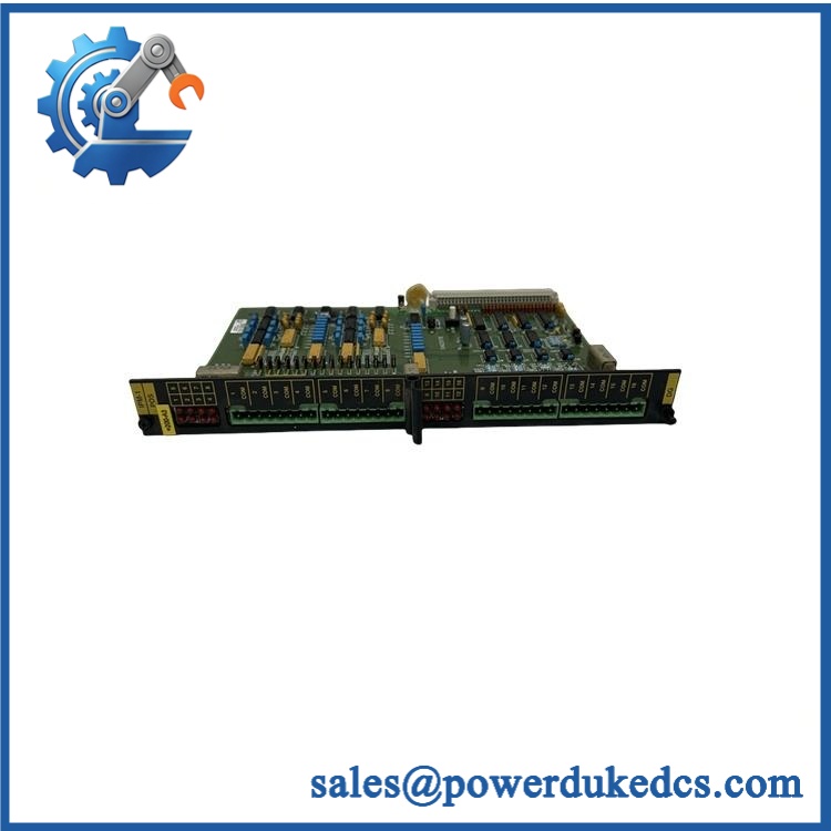
DEIF PCM4.4
Procurement & Lifecycle FAQ
Is the DEIF .4 genuinely in stock, and what is the emergency-shipping cutoff?
Availability must be checked against physical inventory and the specific unit allocated to the order. Request current identification-label photographs, the condition grade, completed test records, and a written dispatch commitment. Same-day shipment depends on stock allocation, order approval, payment clearance, packing, export documentation, and carrier pickup times.
How do you verify the authenticity and condition of a legacy .4?
Request photographs of the module label, PCB markings, connectors, and visible components. Confirm whether the unit is new surplus, used, or tested refurbished. Ask for the available inspection and functional-test records for that particular unit. Where traceability is required, request supporting documentation; visual inspection alone cannot conclusively establish authenticity.
Are there firmware or compatibility issues engineers should check before issuing the PO?
Yes. Confirm the .4 designation, hardware revision, main controller model, rack configuration, ARCNET connection type, and existing application requirements. Preserve the original configuration before replacement and verify controller recognition and extension-rack communication afterward. Do not install a .3 or another module type as a substitute without formal engineering approval.
What warranty and return terms apply to the DEIF .4?
The quotation or pro forma invoice should specify the warranty period, covered defects, dead-on-arrival reporting window, and return authorization process. For used or surplus units, establish the functional acceptance criteria before purchase. Clarify whether commissioning failures are covered and whether return eligibility excludes incorrect wiring, unauthorized modification, or damage during installation.
Is replacing the .4 more cost-effective than migrating the Delomatic 400 system?
A verified like-for-like replacement can avoid immediate controller migration, application redevelopment, wiring changes, and extended commissioning. Compare the landed cost of the replacement with the full migration cost, including engineering, testing, downtime, and operator training. Because this is legacy equipment, also evaluate the availability of future spares and the operational consequences of another module failure. A replacement can solve an immediate shortage without eliminating the longer-term lifecycle risk.