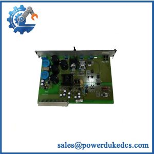
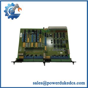
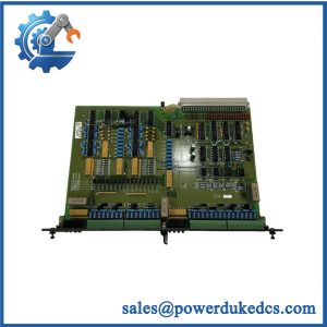
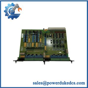
Description
-
Brand: DEIF
-
Model Designation: DELOMATIC-3 DGU2
-
Product Type: Marine generator control and protection system unit
-
Lifecycle Status: Obsolete platform; DEIF documentation lists Delomatic-3 as no longer for sale
-
Core Function: Generator monitoring, protection, synchronization, load sharing, and marine power management
-
Top 3 Technical Specs:
-
System Power Supply: 24 VDC, +30% / -25%; maximum 32 VDC, according to published Delomatic-3 system specifications
-
Voltage Measurement: Up to 690 VAC direct, with other measurement ranges available through voltage transformers
-
Frequency Measurement: 40–70 Hz; published system-level measurement accuracy Class 1 to IEC 688
-
-
System Architecture: 19-inch dual-height DGU rack with configurable plug-in modules
-
Communication: ARCnet over coaxial cable between DGUs and control panels; other interfaces depend on installed modules
-
Protection Rating: IP20 for modules installed in the DGU rack
-
Stock and Condition: Physical quantity, hardware configuration, and condition require confirmation
-
Replacement Status: Exact configuration verification required; DM-4 Marine is a potential modernization route, not an automatic drop-in replacement
-
Procurement Priority: Legacy marine power management maintenance and generator control system restoration
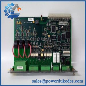
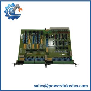
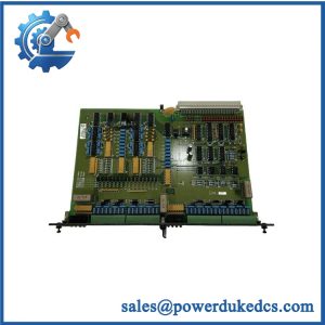
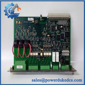
Identification note: DGU2 may identify a particular generator unit within an installed system rather than a complete orderable part number. Confirm the rack identification, installed module codes, and project configuration before requesting a replacement.
Obsolescence & Supply Chain Deep Dive
When a marine generator control system develops a hardware fault, sourcing the correct replacement becomes increasingly difficult after the original platform reaches end of life. DEIF’s published Delomatic-3 documentation identifies the system as no longer for sale, and DEIF has reported that spare parts for the legacy platform are no longer stocked through its standard supply channel. The system was designed for generator control and protection, including synchronization, load sharing, electrical measurement, and power management for up to eight parallel-running generators. Its modular architecture means the required spare must be identified by function and installed module configuration—not by the DGU2 designation alone. Buyers should provide equipment photographs, module codes, revision markings, and the available system project number before requesting a quotation (availability of legacy inventory depends on the specific stock lot).
For vessels that must retain their existing power management architecture, an approved replacement component may reduce expenditure compared with a complete system upgrade. Total cost of ownership (TCO) should include the component price, international freight, technician labor, testing, commissioning, and the expected cost of downtime. A modernization project can introduce application conversion, wiring changes, alarm-system interface adjustments, crew familiarization, and vessel acceptance testing. Those activities may exceed the cost of restoring an existing system with a verified compatible spare. DEIF has documented Delomatic-4 as an upgrade path for Delomatic-3 installations, including projects designed to limit wiring changes. That option requires an application-specific assessment; system architecture, interfaces, and operating requirements must be reviewed before the migration budget is approved.
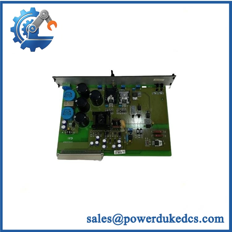
DEIF DELOMATIC-3 DGU2
Compatibility & Replacement Matrix
The replacement classification depends on the exact module or rack assembly being purchased and the installed Delomatic-3 configuration.
|
Evaluation Item |
Preliminary Assessment |
Required Action |
|---|---|---|
|
Replacement classification |
Conditional like-for-like replacement within the verified configuration |
Match the installed module codes, hardware revisions, rack arrangement, and system documentation |
|
Direct drop-in replacement |
Not established from the DGU2 designation alone |
Confirm the complete equipment identification and approved replacement instructions |
|
Software compatibility |
Configuration-dependent |
Verify project software, parameter settings, PROM version, and applicable module requirements |
|
Hardware modification |
Undetermined until the target configuration is identified |
Check rack dimensions, connector arrangement, terminal assignments, and module positions |
|
System power supply |
Published Delomatic-3 system specification: 24 VDC, +30% / -25%, maximum 32 VDC |
Verify the actual power supply module and its requirements |
|
Generator voltage measurement |
Up to 690 VAC direct under the published system specification; alternative ranges through voltage transformers |
Confirm the fitted measurement module and transformer ratios |
|
Communication compatibility |
ARCnet between DGUs and control panels; additional interfaces depend on installed modules |
Match the communication module, wiring, and control panel configuration |
|
Like-for-like exchange labor |
Preliminary planning allowance: 4–8 technician-hours for identification, replacement, and initial checks |
Excludes extended fault diagnosis, vessel access constraints, and full system commissioning |
|
Delomatic-4 migration |
Engineering-led modernization project |
Scope application changes, wiring, interface adaptation, validation, and vessel acceptance |
|
Cost estimate |
Quotation and configuration review required |
Include parts, freight, labor, testing, outage exposure, and any system integration work |
Field Traps: Checks Before Purchase
Module configuration mismatch
A Delomatic-3 DGU is a configurable rack, not necessarily a single standardized circuit board. Its fitted modules can include the PSM-1 power supply, CM-2 control module, SCM-1 or SCM-2 synchronization modules, CRM-1 current relay module, IPM-1 input module, OPM-1 binary output module, and AOM-1 analog output module. Verify the exact installed module and revision before ordering. A matching rack designation does not guarantee that the internal configuration is equivalent.
Power and measurement wiring
The published 24 VDC supply specification applies to the Delomatic-3 system; the actual power requirements must be checked against the installed supply module. Measurement circuits also depend on voltage transformer ratios, current transformer ratings, and the fitted measurement module. Incorrect wiring or measurement scaling can affect generator protection and synchronization. Obtain the relevant schematics and approved replacement instructions before installation.
Communication and software differences
Delomatic-3 DGUs and control panels communicate over ARCnet using coaxial cable. Some CM-2 configurations also support RS-232, RS-422, or RS-485 communication modules. These interfaces are configuration-dependent. Verify the installed hardware, communication settings, and application parameters rather than assuming that two visually similar control modules will communicate correctly.
Quality Assurance & Testing SOP
Pre-shipment quality assurance should establish the identity, physical condition, and functional status of the actual DEIF DELOMATIC-3 DGU2-related equipment. The test scope must match the confirmed module configuration and available approved test equipment.
|
QA Stage |
Inspection or Test Action |
Acceptance Criteria |
|---|---|---|
|
Product identification |
Conduct an OEM anti-counterfeit visual inspection of labels, model markings, serial numbers where present, revision details, and module designations |
Identification agrees with the quoted configuration; discrepancies are documented |
|
Physical inspection |
Examine the rack, PCB assemblies, connectors, mounting features, terminals, solder joints, and visible components |
No disqualifying damage, corrosion, contamination, or unexplained modifications |
|
Configuration verification |
Compare the installed module arrangement against the available bill of materials and system documentation |
Module positions and identification are recorded |
|
Electrical pre-check |
Inspect the power supply and relevant circuits; perform electrical measurements using an approved procedure |
Results meet the applicable module specifications |
|
Power-on self-test (POST) |
Apply power using an appropriate test arrangement; inspect available diagnostic indicators, including ERR/RUN LEDs only where fitted and documented |
Startup behavior agrees with the applicable technical documentation |
|
Controller function test |
Test the CM-2 control module in a compatible setup where supported |
Expected startup and diagnostic responses are recorded |
|
Measurement verification |
Apply suitable test signals to the fitted synchronization and measurement modules |
Voltage, current, frequency, and other tested values meet the specified acceptance criteria |
|
Communication test |
Check ARCnet communication and other fitted interfaces using compatible test equipment |
Expected communication and diagnostic responses are obtained |
|
I/O load testing |
Test fitted input and output modules using suitable signal simulators and rated loads |
Tested channels perform according to the applicable module specifications |
|
Protection-function checks |
Verify supported relay and protection functions under an approved test procedure |
Recorded results meet the agreed test criteria; no unapproved live-system testing |
|
Final inspection |
Record the part number, module configuration, visible revisions, completed tests, photographs, and packaging condition |
Unit-specific inspection record available for buyer review |
Test scope and limitations: A bench test does not establish full generator or vessel-level compatibility. If the original application, compatible rack, or approved test equipment is unavailable, the inspection report must identify which functions could not be verified.
Never force generator breaker commands, bypass protective functions, or apply test signals to an operating vessel’s control system without an approved procedure. Final restoration should follow the vessel’s maintenance and commissioning requirements, with qualified personnel verifying the relevant protection and synchronization functions.
Procurement & Lifecycle FAQ
Is the DEIF DELOMATIC-3 DGU2 genuinely in stock, and what is the emergency shipping cutoff?
Availability must be confirmed against the actual inventory lot. Request the available quantity, complete module configuration, condition, revision details, and current photographs before issuing the purchase order.
Emergency dispatch depends on order approval, payment arrangements, completion of agreed inspection steps, destination, and carrier collection schedules. Request a written dispatch cutoff and committed shipping date. Same-day shipment should not be assumed without confirmation.
How do you verify the authenticity and condition of obsolete DEIF equipment?
The inspection process should cover product labels, module codes, visible revisions, connectors, PCB condition, and functional testing where a compatible setup is available. Request photographs of the actual unit and a unit-specific inspection report.
The quotation should distinguish new original stock, new surplus, used equipment, and refurbished inventory. These conditions are not interchangeable. Supporting traceability records should be provided where available, and any limitations in functional testing should be disclosed before purchase.
Are there firmware or configuration compatibility issues engineers should review before issuing the purchase order?
Yes. Confirm the installed module codes, control module revision, PROM version, project configuration, measurement settings, communication modules, and control panel arrangement.
A replacement should not be treated as compatible solely because its outer housing or model designation resembles the installed unit. Where an application has been modified for a particular vessel, the engineering team should verify those modifications against the proposed spare before installation.
What warranty and return policies apply?
The warranty period, coverage, exclusions, and return eligibility should be documented in the quotation or pro forma invoice before purchase. Confirm the defect reporting deadline, the requirements for a defective-on-arrival claim, and the procedure for evaluating a returned item.
Use an agreed return merchandise authorization (RMA) process. Preserve product labels, module markings, packaging, and test records so the delivered equipment can be matched to the purchase order.
Should we replace the DELOMATIC-3 or upgrade to Delomatic-4?
The decision depends on the equipment condition, spare availability, remaining service requirements, and the cost of the proposed migration.
A verified compatible spare may provide the lower-cost route when the existing installation remains serviceable and a suitable module can be sourced. A Delomatic-4 modernization may be more appropriate when legacy parts are difficult to obtain, repeated failures increase downtime exposure, or long-term maintenance planning calls for a platform transition. Compare component cost, engineering hours, wiring changes, application adaptation, testing, commissioning, and vessel downtime before approving either option.
For an accurate quotation, provide the complete equipment identification, project number where available, required quantity, module codes, photographs, delivery destination, and required delivery date. Written confirmation of stock, condition, test scope, warranty, and dispatch timing should form part of the purchasing decision.