

Description
- Brand: Foxboro
- Full Model Number: FBM217 RH914TR
- System/Series Family: Foxboro I/A Series / Foxboro Evo Standard 200 Series
- One-Sentence Core Function: Redundant-ready 32-channel discrete input module for monitoring field contact and voltage signals
- Top 3 Hardcore Specs: 32 discrete input channels; redundant-ready architecture; 2 Mbps redundant Module Fieldbus
- Stock Status: Stock condition, hardware revision, and termination assembly to be confirmed
Module 3: Technical Product Introduction
A single failed discrete input card can remove dozens of field status signals from a DCS at once: valve limit switches, breaker positions, motor permissives, alarms, and interlocks are all potential casualties. The Foxboro FBM217 RH914TR is a 32-channel discrete input module designed for the Standard 200 Series subsystem and is identified by Schneider Electric as a redundant-ready FBM. It communicates with the associated Fieldbus Communication Module or Field Control Processor through redundant 2 Mbps Module Fieldbus A/B paths. The RH914TR part number supersedes the earlier P0914TR designation.
The FBM217 is highly dependent on its termination assembly for the actual field-input electrical characteristics. Schneider documentation lists several termination configurations, including voltage-monitor and contact-sense arrangements with different field voltage ranges and isolation behavior. The module itself is approximately 102 mm high, 45 mm wide, and 104 mm deep, with a mass of about 284 g. Its documented operating temperature is −20°C to +70°C, while supported termination assemblies and input ranges must be selected according to the installed application.
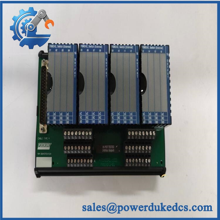
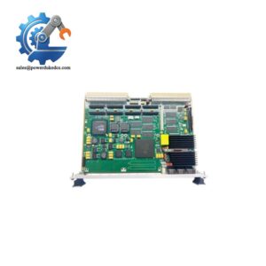
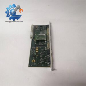
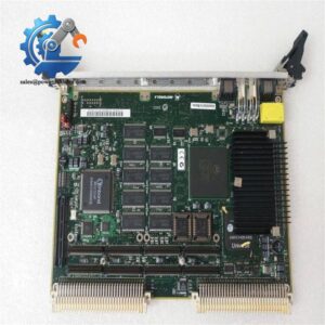
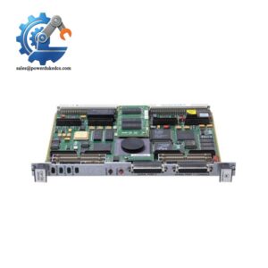
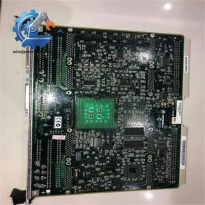
Foxboro FBM217 RH914TR
Module 4: Application Scenarios & Field Realities
- On a refinery motor-control panel, the FBM217 can collect multiple run, trip, breaker, and permissive contacts without consuming an excessive number of I/O positions. The 32-channel density is useful when marshalling cabinets already have large numbers of discrete status points, but the actual field voltage must be matched to the selected termination assembly.
- For valve-position feedback and shutdown permissives, the redundant-ready design becomes relevant when the DCS architecture requires high availability. Schneider specifies that redundant FBM217 modules occupy adjacent odd/even baseplate positions and use the appropriate redundancy adapter, identified as RH926ZY.
- In mixed-voltage field marshalling, do not assume all 32 inputs share one universal electrical range. The FBM217 family supports multiple termination arrangements, including AC voltage-monitor and DC contact-sense configurations. Selecting the wrong termination assembly can change the input threshold, excitation method, and isolation scheme.
- During a legacy Foxboro upgrade, RH914TR should be treated as the exact module identifier rather than relying only on “.” Schneider’s documentation identifies RH914TR as the current part number, superseding P0914TR. That distinction is useful when reconciling old drawings, warehouse records, and newly sourced spares.
Module 5: Migration, Compatibility & Installation Traps
Replacement Matrix
Replacement Classification: Drop-in Replacement Within the Matching Architecture — Termination Configuration Must Match
A like-for-like replacement is normally a direct hardware exchange when the existing system uses the same Standard 200 Series architecture, baseplate, termination assembly, fieldbus arrangement, and application configuration. Schneider Electric explicitly identifies RH914TR as the module part number and RH926ZY as its corresponding redundancy adapter.
These references represent the same module family with superseding P0914TR in the current documentation. Nevertheless, verify the physical revision and installed termination hardware before replacing an older unit in a safety- or availability-critical application.
⚠️ Field Traps — Watch Out
1. Termination assembly determines the field interface: The can be associated with different termination assemblies supporting different input arrangements. Schneider documents 240 VAC voltage-monitoring, 240 VAC contact-sense, and DC voltage/contact-sense configurations among the available options. The module part number alone is therefore insufficient to determine the complete field wiring specification.
2. Redundant slot arrangement: A redundant pair must occupy adjacent odd/even baseplate positions, such as 1–2, 3–4, 5–6, or 7–8, and use the appropriate redundancy adapter. Installing the modules in arbitrary adjacent slots can create a hardware configuration error.
3. Legacy versus current identification: Older drawings may show P0914TR, while current documentation uses . Confirm the complete hardware reference before purchasing, particularly when warehouse records contain a mixture of legacy Foxboro and current Schneider Electric nomenclature.
Module 6: Quality Assurance SOP
Each Foxboro should pass a documented inspection and functional test before shipment.
- OEM identification visual inspection: Verify Foxboro identification, designation, part number, serial number, hardware revision, front label, connectors, and module condition.
- Legacy-reference verification: Record whether the unit is marked or the superseded P0914TR designation so the shipment record corresponds with the customer’s installed documentation.
- Mechanical inspection: Examine the housing, connector interfaces, mounting lugs, guide surfaces, LED indicators, and PCB condition for impact, corrosion, contamination, or repair evidence.
- Power verification: Apply the approved 24 VDC module supply using a compatible Standard 200 Series test setup and confirm stable startup behavior.
- Power-on self-test (POST): Verify initialization, status indication, and expected diagnostic behavior before connecting production field circuits.
- 32-channel input test: Exercise every input independently using a controlled test fixture and confirm correct state recognition at the module and supervisory-system levels.
- Input-threshold verification: Test representative channels against the electrical characteristics applicable to the installed termination assembly. Do not use one generic voltage threshold for every configuration.
- Contact-sense verification: For contact-sense applications, verify the expected open/closed response using the correct external or internal excitation arrangement specified by the selected TA.
- Module Fieldbus communication test: Verify communication with the associated FCM/FCP through the redundant 2 Mbps A/B Module Fieldbus paths.
- Redundancy test: Where supplied for redundant service, test the pair with the RH926ZY adapter and verify correct takeover behavior under the authorized procedure.
- Termination verification: Record the exact termination assembly part number and confirm that its input range and isolation method match the customer’s application.
- Extended operating test: Run the module under controlled load within the documented −20°C to +70°C operating range while monitoring field input states and Module Fieldbus communications.
- Final QC record: Retain identification photographs, hardware revision, termination-assembly reference, 32-channel test results, communication results, redundancy results where applicable, test-equipment identification, and final QC approval.
The critical procurement detail for FOXBORO is not simply “32 digital inputs.” The module is a 32-channel discrete input FBM, and the actual field electrical behavior depends on the selected termination assembly. Schneider Electric identifies as the current part number and specifies redundant 2 Mbps Module Fieldbus communication, while its termination documentation defines the supported voltage-monitor and contact-sense configurations. Match the module, termination assembly, baseplate position, and redundancy hardware before releasing the spare to the field.



 Start Chat


