

Description
- Brand: Foxboro
- Full Model Number: P0926GU FBM230
- System/Series Family: Foxboro I/A Series / Foxboro Evo Standard 200 Series
- One-Sentence Core Function: Eight-channel analog input module for isolated 4–20 mA and related process-current signals
- Top 3 Hardcore Specs: 8 analog input channels; 4–20 mA process-current input; redundant 2 Mbps Module Fieldbus
- Stock Status: Stock condition, hardware revision, and termination assembly to be confirmed
Module 3: Technical Product Introduction
A failed analog input module can corrupt several critical process measurements at once: pressure, temperature, flow, level, or analyzer signals may disappear from the DCS even though the transmitters in the field remain healthy. The Foxboro FBM230, identified by part number P0926GU, is an eight-channel analog input interface for the Standard 200 Series architecture. It acquires field analog signals and transfers the resulting process data through the redundant Module Fieldbus to the associated Fieldbus Communication Module or Field Control Processor. Each input is designed for isolated field interfacing, making channel-level diagnosis much easier than with a shared unisolated input arrangement.
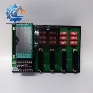
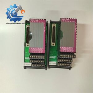
For replacement work, the termination assembly must be treated as part of the electrical specification. The FBM230 family is offered with application-specific termination arrangements, so the short module designation does not by itself establish the exact transmitter input range, wiring topology, or excitation method. A production replacement should therefore match the installed FBM230 part number, termination assembly, field wiring, and configured channel type. —especially in older I/A Series cabinets where drawings can remain unchanged for years while individual hardware revisions have moved forward.
Module 4: Application Scenarios & Field Realities
- On refinery pressure and flow transmitters, the FBM230 provides centralized acquisition of analog process values while maintaining channel separation at the I/O interface. Before commissioning, compare transmitter loop current, marshalling wiring, and the expected engineering range; a stable 4–20 mA loop can still report an incorrect process value if the software scaling is wrong.
- For temperature and level measurement loops, the practical issue is termination compatibility. The module designation alone does not tell you how the field device is terminated, so verify the exact termination assembly and its approved wiring diagram before reusing existing marshalling hardware.
- Within redundant Foxboro I/O architectures, two compatible FBM230 modules can be arranged as a redundant pair where the system design permits it. The physical baseplate positions and redundancy adapter must follow the Foxboro installation rules; redundancy is not created simply by installing two identical cards.
- During a legacy control-system spare replacement, record the original module’s hardware revision and complete part number before removing it. P0926GU is the useful procurement identifier here. Keep that exact designation in the warehouse record rather than reducing the item to the generic “” label.
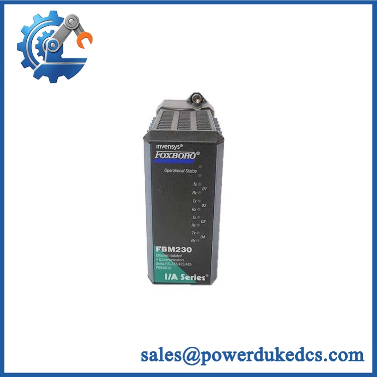
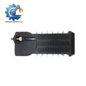
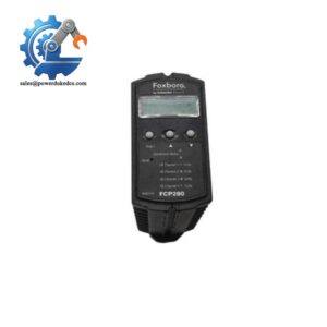
Foxboro FBM230 P0926GU
Module 5: Migration, Compatibility & Installation Traps
Replacement Matrix
Replacement Classification: Drop-in Replacement Within the Matching Configuration — Termination and Revision Must Match
A like-for-like P0926GU FBM230 replacement is generally suitable as a direct hardware exchange when the installed system already uses the same architecture, compatible baseplate, field termination, Module Fieldbus arrangement, and application configuration. The replacement should be checked against the existing termination assembly before energization because the field interface is not determined solely by the common family name.
→ another FBM23x variant: Do not assume interchangeability. Related Foxboro analog-input modules can use different electrical interfaces, input ranges, or termination arrangements. A similar housing and connector interface does not establish electrical compatibility.
⚠️ Field Traps — Watch Out
1. Termination mismatch: The termination assembly determines the actual field wiring interface presented to the module. Reusing a visually similar termination assembly without checking its part number can result in incorrect channel scaling or an electrically incompatible transmitter loop.
2. Analog-loop polarity and scaling: Verify loop polarity, transmitter supply arrangement, input burden, and DCS engineering range before return to service. A module can pass a basic electrical check while the control-system value remains wrong because the channel configuration or range does not match the field transmitter.
3. Redundancy position: Where the application uses redundant modules, confirm the required odd/even baseplate positions and redundancy adapter arrangement from the Foxboro system documentation. Do not infer the redundant pairing solely from module location.
Module 6: Quality Assurance SOP
Each Foxboro P0926GU should pass identification, electrical, communication, and channel-level testing before shipment.
- OEM identification visual inspection: Verify Foxboro markings, designation, P0926GU part number, serial number, hardware revision, front label, connector condition, and module housing.
- Mechanical inspection: Examine the housing, fieldbus connector, baseplate interface, mounting surfaces, status LEDs, and exposed PCB areas for cracks, contamination, corrosion, or previous repair.
- Termination verification: Record the exact termination assembly associated with the test unit and compare it with the customer’s existing installation documentation.
- Power verification: Install the module in an approved Standard 200 Series test arrangement and verify stable operation under the specified module supply.
- Power-on self-test (POST): Confirm normal startup, module identification, status indication, and diagnostic behavior before applying process-signal inputs.
- Eight-channel analog-input test: Apply calibrated representative current signals to all eight inputs and record the measured DCS values for low-range, mid-range, and high-range points.
- 4–20 mA verification: Exercise representative channels at approximately 4 mA, 12 mA, and 20 mA and compare the measured result against the configured engineering scale.
- Channel isolation check: Stimulate one channel while monitoring the others to confirm that the test signal does not create an unintended response on adjacent inputs.
- Open-loop and fault test: Simulate an approved transmitter-loop fault and verify the expected diagnostic behavior at the module and supervisory-system levels.
- Module Fieldbus communication test: Verify stable communication through the redundant 2 Mbps A/B Module Fieldbus interface using the authorized test configuration.
- Redundancy verification: Where the supplied unit is intended for redundant service, test the redundant pair and confirm the expected takeover or diagnostic behavior under a controlled test procedure.
- Thermal observation: Run an extended functional test while monitoring input stability, fieldbus communications, and diagnostic status under the applicable operating-temperature conditions.
- Final QC record: Retain complete part-number photographs, hardware revision, termination-assembly reference, eight-channel measurement results, communication results, redundancy results where applicable, test-equipment identification, and final QC approval.
The key spare-parts control for FOXBORO is exact configuration matching. The is an eight-channel analog input module, but the usable field interface depends on the associated termination and system configuration. Preserve the complete identifier, verify the termination hardware, and validate all eight channels before releasing the spare for a production I/A Series or Foxboro Evo installation.




 Start Chat


