

Description
- Brand: HIMA
- Full Model Number: F60DIO24/1601 / DIO 24/16 01
- System/Series Family: HIMatrix F60 modular safety controller
- Core Function: 24-channel safety digital input and 16-channel safety digital output interface for field devices
- Top 3 Hardcore Specs: 24 DI + 16 DO; 24 VDC supply; 2 A per output channel / 8 A maximum module load
- Stock Status: Verify current New Surplus, Factory Sealed, or Fully Tested Refurbished condition before order
Module 3: Technical Product Introduction
A failed mixed I/O card can affect both field status acquisition and the actuator side of a safety application. The HIMA F60DIO24/1601, identified in HIMA documentation as DIO 24/16 01, is a module for the modular F60 HIMatrix system, providing 24 galvanically separated digital inputs and 16 galvanically separated digital outputs. It installs in F60 subrack slots 3 through 8, while slots 1 and 2 are reserved for the power supply and central module. HIMA’s documentation also identifies the module for safety-related applications up to SIL 3 under IEC 61508, IEC 61511, and IEC 62061, with Cat. 4 and PL e under EN ISO 13849-1; HIMA’s certification records also list the DIO 24/16 01 within the applicable HIMatrix certification scope.
The electrical data leaves little room for casual substitution. The module operates from 24 VDC, -15% to +20%, with stated internal consumption of approximately 380 mA at 24 VDC plus 150 mA at 3.3 VDC. The 24 inputs accept nominal 24 VDC signals with a 10–30 V high-level range, while the 16 outputs provide 18.4–26.8 VDC and can switch 2 A per channel, subject to an 8 A maximum total module load. Each output is permanently short-circuit protected, with an internal voltage drop of up to 2 V at 2 A. That combination makes the module suitable for high-density safety I/O, but the 8 A aggregate limit must be checked against the actual simultaneous load before commissioning.
Module 4: Application Scenarios & Field Realities
- On a HIMatrix F60 safety rack handling shutdown permissives, the DIO 24/16 01 can acquire 24 discrete field states while controlling 16 output circuits from the same module. The important detail is the slot architecture: this card belongs in F60 positions 3–8, not in the power-supply or CPU positions.
- For emergency-stop and monitored contact circuits, outputs O1 through O8 can be configured as pulsed outputs for line-control functions. HIMA documents this arrangement for detecting short circuits and open circuits on safety-related input wiring, including emergency-stop circuits. Those pulsed outputs are specifically not to be used as safety-related outputs.
- When several solenoids or other 24 VDC actuators operate at once, the individual 2 A rating is only part of the calculation. If the combined output demand exceeds 8 A, the module switches all outputs off for 10 seconds and performs a new test. A cabinet engineer should therefore calculate simultaneous demand rather than simply checking each load independently.
- During troubleshooting of an apparently dead channel, check the module diagnostics before replacing hardware. The front panel provides RUN and ERR indicators plus individual I/O LEDs; HIMA specifies that a module or detected channel fault activates the ERR indication and causes the relevant output to enter the safe de-energized state.
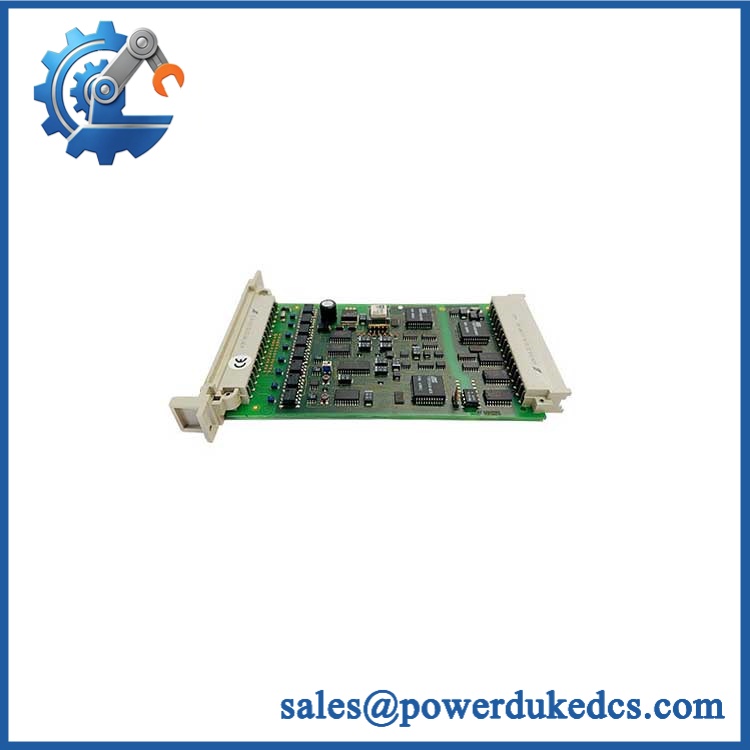
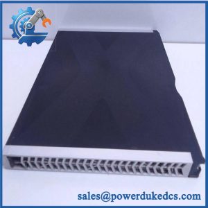
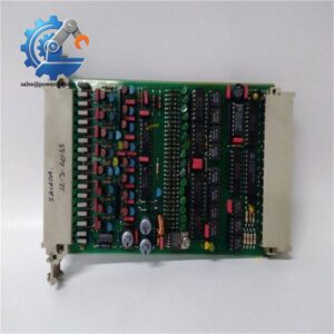
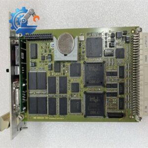
HIMA F60DIO24/1601
Module 5: Migration, Compatibility & Installation Traps
Replacement Matrix
Exact F60DIO24/1601 / DIO 24/16 01 configuration: Drop-in Replacement
For an existing F60 installation using the same DIO 24/16 01 variant, matching terminal arrangement, field voltage, and approved hardware configuration, the replacement is normally a direct module exchange without changing the application logic.
DIO 24/16 01 revision or firmware change: Software Compatible / Verification Required
The physical module may be compatible while firmware, hardware revision, or project configuration still requires verification. HIMA’s type-label documentation identifies the hardware and firmware revision indices as part of the module identification data.
Different F60 I/O family: Hardware Modification Required unless explicitly approved
The F60 family includes different DI, DO, DIO, analog, and communications modules. A different channel configuration should not be treated as equivalent simply because it fits the same basic F60 rack.
⚠️ Field Traps (Watch Out)
Total-current trap: Each output can handle up to 2 A, but the module is limited to 8 A total across its outputs. HIMA also specifies a defined overload reaction: an overloaded output is switched off for 10 seconds, and a module-wide load above 8 A causes all outputs to be switched off for 10 seconds before retesting.
Line-control trap: O1–O8 can be used as pulsed outputs for line monitoring, but those pulse outputs must not be assigned as ordinary safety outputs. During migration, review the SILworX or ELOP II Factory configuration and the field wiring together; a terminal that looks electrically correct can still be assigned the wrong safety function.
Power-supply trap: The module requires a 24 VDC supply with safe isolation. HIMA’s environmental data specifies Protection Class III and a supply consistent with IEC 61131-2 requirements. Verify the F60 power module capacity before increasing output loading.
Module 6: Quality Assurance SOP
Pre-Shipment QA Protocol for HIMA F60DIO24/1601
- Step 1 — Identity Verification: Confirm HIMA marking, F60DIO24/1601 designation, DIO 24/16 01 product identification, part number, production information, hardware revision, and firmware revision where accessible.
- Step 2 — OEM Anti-Counterfeit Visual Inspection: Check the label format, barcode, housing, PCB markings where accessible, front-panel legends, terminal interfaces, and assembly quality for inconsistencies or signs of unauthorized modification.
- Step 3 — Mechanical Inspection: Inspect the module housing, card guides, terminal plugs, locking features, front-panel indicators, and connector surfaces for cracks, deformation, corrosion, contamination, or bent contacts.
- Step 4 — Supply Verification: Confirm the test fixture provides the specified 24 VDC supply through an appropriate safe-isolated source before energizing the module.
- Step 5 — Power-On Self-Test: Apply controlled power and verify the RUN and ERR indicators, monitoring the startup sequence for abnormal diagnostic behavior. HIMA specifies RUN as the operating indication and ERR as the fault indication.
- Step 6 — Digital Input Test: Exercise all 24 inputs with controlled 24 VDC signals. Record high-level recognition, low-level release, input LED response, and diagnostic status.
- Step 7 — Digital Output Test: Test all 16 outputs individually using controlled loads. Verify output voltage, switching response, output LED indication, and absence of abnormal current draw.
- Step 8 — Protection Test: Where the laboratory setup permits, perform controlled short-circuit or overload simulation and verify the documented protection response without exposing the production field circuit to an uncontrolled fault.
- Step 9 — Line-Control Verification: Where the unit is configured for monitored safety wiring, verify the pulse-output and digital-input relationship using an approved test fixture. Confirm that the application does not treat the pulsed outputs as safety-related outputs.
- Step 10 — Final QC Record: Record complete model identification, hardware and firmware revisions, input-channel results, output-channel results, protection behavior, LED status, visual inspection, test date, and final QC disposition before packaging.
Technical Verification Note: HIMA’s own DIO 24/16 01 manual identifies the module as a 24-input / 16-output F60 HIMatrix module, with galvanic separation from the I/O bus, installation in F60 slots 3–8, 24 VDC operation, 260 g nominal weight, 6 RU / 4 HP space requirement, 2 A per output channel, and an 8 A maximum total output load. HIMA’s certification material independently identifies the HIMatrix F60 DIO 24/16 01 as a safety-related 24/16-channel I/O module.



 Start Chat


