

Description
- Brand: HIMA
- Full Model Number: H7201
- System/Series Family: HIMA HIMax
- Core Function: Feed-line and distribution fuse board for 24/48 VDC HIMax power distribution
- Top 3 Hardcore Specs: 24/48 VDC supply; 92 A maximum current; SELV/PELV distribution
- Board Type: Feed Line and Distribution Fuse Board
- Protection: Fused distribution of DC supply circuits
- Hazardous-Area Approval: FM nonincendive, Class I Division 2, Groups A-D; T4A/T5/T6 classifications apply under stated conditions
- Stock Status: New Surplus or Fully Tested Refurbished; batch-specific availability
HIMA identifies H7201 as the HIMax Feed Line and Distribution Fuse Board. HIMA’s current certification documentation specifies SELV/PELV operation for 24/48 VDC power distribution with a maximum current of 92 A.
Module 3: Technical Product Introduction
A DC power fault inside a HIMax cabinet does not always originate at the power supply itself. The distribution stage is where incoming power is divided into protected circuits, so a degraded fuse board, incorrect fuse arrangement, or damaged feed connection can interrupt multiple downstream loads. HIMA’s H7201 is the Feed Line and Distribution Fuse Board used with HIMax systems, providing the cabinet-level interface for distributing 24/48 VDC power through fused circuits. HIMA documentation identifies the board as part of the HIMax accessory and power-distribution architecture.
The useful rating for maintenance planning is its current capacity. HIMA’s FM documentation specifies H7201 as a SELV/PELV distribution fuse board for 24/48 VDC with a maximum current of 92 A. That makes it a power-distribution component rather than an active CPU, I/O, or communication module. During replacement, the critical checks are therefore supply voltage, total current demand, fuse selection, terminal arrangement, conductor sizing, and the exact HIMax cabinet design — not firmware compatibility.
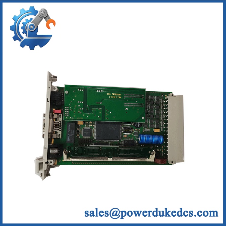
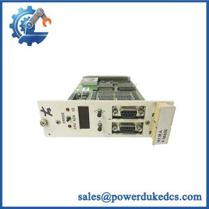
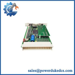
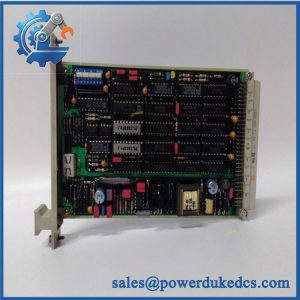
HIMA H7201
Module 4: Application Scenarios & Field Realities
- Inside a HIMax safety-control cabinet with several downstream DC loads, H7201 provides the common feed and fused distribution point between the incoming 24/48 VDC supply and individual protected circuits. The 92 A maximum rating is important when calculating worst-case cabinet loading rather than relying on nominal operating current.
- When a cabinet contains redundant or separately protected supply branches, the fuse-distribution architecture helps maintenance technicians isolate a failed branch without treating every downstream module as suspect. The actual branch arrangement, however, must be checked against the cabinet wiring diagram before removing or moving any fuse.
- For installations operating in a classified hazardous area, H7201’s approval conditions become part of the installation requirements. HIMA’s FM documentation identifies the board as nonincendive for Class I, Division 2, Groups A, B, C and D, with the applicable temperature code dependent on the specified equipment configuration.
- During cabinet refurbishment or power-system migration, do not substitute a generic fuse-distribution board merely because the DC voltage matches. is documented as a HIMax accessory, and mechanical arrangement, circuit segregation, fuse characteristics, conductor termination, and certification conditions all have to remain appropriate for the final assembly.
Module 5: Migration, Compatibility & Installation Traps
Replacement Matrix
Replacement classification: Drop-in Replacement only for an existing HIMA installation when the cabinet layout, terminals, fuse configuration, voltage class, conductor arrangement, and system documentation are unchanged.
Software compatibility: Not applicable. is a passive power-distribution and fuse-board assembly; there is no user application firmware to download or recompile.
Cross-model replacement: Hardware modification required unless documented as a direct equivalent. HIMA lists and H7202 as separate distribution boards. is specified for feed-line and distribution use, while H7202 is a distribution fuse board with a different current rating. They should not be treated as interchangeable simply because both operate in 24/48 VDC systems. HIMA’s documentation specifies H7202 at a maximum of 64 A versus 92 A for .
Field Traps — Watch Out
1. Total current is a cabinet-design parameter, not just a fuse-board number. is rated up to 92 A, but the installation remains limited by the upstream power supply, cabling, terminals, protection devices, ambient conditions, and the ratings of the connected branches. Never interpret 92 A as a guaranteed continuous load for every cabinet arrangement.
2. Fuse selection must match the original protection scheme. Replacing a blown fuse with a higher-rated device can defeat branch protection and increase fault energy. Before energizing a replacement board, document each fuse position, rating, characteristic, and destination circuit.
3. Hazardous-area approval has installation conditions. HIMA’s FM certificate states that the equipment must be installed in accordance with the enclosure, mounting, spacing, and segregation requirements of the ultimate application. Therefore, a certified does not by itself certify an entire rebuilt cabinet.
Module 6: Quality Assurance SOP
Pre-Shipment Inspection Protocol for HIMA
- OEM identity inspection: Verify HIMA marking, exact designation, identification data, terminal layout, fuse positions, and board construction against available HIMA documentation.
- Mechanical inspection: Check the PCB or distribution assembly, mounting points, terminal blocks, fuse holders, labels, insulating barriers, and enclosure interfaces for cracks, deformation, corrosion, contamination, or unauthorized modification.
- Fuse-holder inspection: Verify each fuse position is mechanically sound, correctly retained, and free from signs of overheating, arcing, carbonization, or loose contacts.
- Terminal inspection: Check every accessible power terminal for mechanical integrity, correct hardware, discoloration, and evidence of thermal stress.
- Continuity verification: Perform controlled point-to-point continuity testing through the applicable feed and distribution paths, documenting open circuits and unexpected resistance.
- Insulation verification: Where permitted by the applicable HIMA procedure, perform an insulation-resistance test between appropriate circuits and protective earth using a controlled test voltage.
- Power-distribution simulation: Connect the board to a protected laboratory DC source and verify correct voltage distribution across the relevant protected outputs without exceeding the configured fuse ratings.
- Fuse protection verification: Confirm installed or supplied fuse ratings against the approved configuration and record each fuse location individually.
- Thermal observation: Operate representative load branches and monitor terminals, fuse holders, and high-current paths for abnormal temperature rise.
- Certification review: Verify that identification and approval markings correspond to the intended application; HIMA documentation identifies for 24/48 VDC SELV/PELV distribution and provides FM hazardous-area conditions.
- Final QC record: Record model, identification number, fuse configuration, measured voltages, continuity results, insulation-test results where applicable, load-test observations, test date, and inspector approval.
- ESD and mechanical packaging: Protect the board, terminals, fuse holders, and insulating components from ESD, impact, contamination, and moisture during final packing and shipment.
Engineering procurement note: HIMA’s own product documentation is clear that is a power-distribution accessory, not an active control module. For purchasing and replacement purposes, verify the complete cabinet drawing and the board’s exact fuse/terminal configuration before treating a used or surplus as a direct substitute.



 Start Chat


