

Description
- Brand: HIMA
- Full Model Number: F3322
- System/Series Family: HIQuad H41q / H51q I/O system
- Core Function: 16-channel digital output module for switching 24 VDC field loads with individual short-circuit protection
- Top 3 Hardcore Specs: 16 digital outputs; 24 VDC; 0.5 A / 12 W per output
- Stock Status: Verify current New Surplus, Factory Sealed, or Fully Tested Refurbished condition before order
Module 3: Technical Product Introduction
An output-module fault can stop field actuators even when the HIMA processor and input side remain healthy. The HIMA F3322 is a 16-channel digital output module for HIQuad X and legacy H41q/H51q I/O architectures, intended to switch 24 VDC field loads. HIMA’s current certification documentation identifies F3322 as a 16-channel, 24 VDC, 0.5 A output module, while HIMA technical documentation specifies 500 mA capability and up to 12 W for resistive or inductive loads.
The electrical limits are important when sizing the replacement. Each output is short-circuit protected, with the current limiter responding above 550 mA; the module itself requires approximately 110 mA from the 5 V supply and 150 mA from the 24 V supply before field-load current is added. A maximum of 10 nominally loaded F3322 modules is specified for one I/O subrack, with no more than 8 A of total output load switched simultaneously. That makes the F3322 a defined load-management component, not simply a 16-point contact block.
Module 4: Application Scenarios & Field Realities
- In an H41q or H51q safety I/O cabinet, the F3322 can drive discrete field loads such as solenoid valves, contactor interfaces, alarm devices, and indicator circuits. The module is designed around 24 VDC output loads, so the external circuit should be checked against the 500 mA channel limit before installation.
- Where inductive loads are switched repeatedly, the per-channel current limitation becomes a practical diagnostic feature. A shorted actuator circuit can force the affected output into current limiting rather than allowing an uncontrolled overload; however, the field wiring and load itself still require inspection before resetting the circuit.
- On a heavily populated I/O subrack, simultaneous load matters more than the nominal number of channels. HIMA documentation limits the simultaneous output load to 8 A, and the standard rack fuse is specified as 4 A slow-blow in the referenced planning data. Exceeding the permitted loading can create a rack-level protection issue even though every individual output remains below 0.5 A.
- During legacy-system replacement, connector and cable identification deserve the same attention as the module itself. HIMA documentation associates with Z7136 / 3322 cable plugs and identifies a 4-SU space requirement, so a physically similar output module should not be assumed electrically interchangeable.
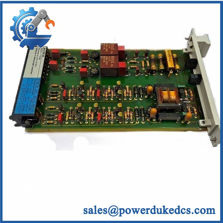
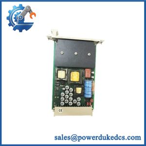
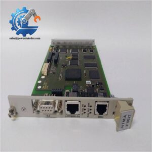
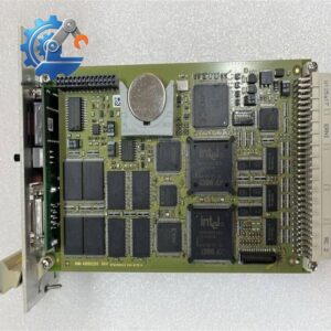
HIMA F3322
Module 5: Migration, Compatibility & Installation Traps
Replacement Matrix
Same configuration: Drop-in Replacement
For an existing installation with matching rack, connector arrangement, field voltage, and hardware configuration, the replacement is normally a direct module exchange without changing the application logic.
Different revision or order-code variant: Software Compatible / Hardware Verification Required
Check the exact nameplate and installed documentation before substitution. HIMA certification records identify as a 16-channel 24 VDC / 0.5 A module, while commercial inventory records may show additional order-code identifiers.
Different HIMA output-module family: Hardware Modification Required unless specifically approved
Relay-output modules and other digital-output families can differ in channel count, field wiring, current capability, monitoring behavior, and terminal configuration. A similar front-panel format is not sufficient evidence of compatibility.
⚠️ Field Traps (Watch Out)
Total-load trap: The 0.5 A rating applies to an individual output. HIMA documentation separately limits the total simultaneous output load to 8 A within the I/O subrack. Calculate the real concurrent load before adding a new to a heavily populated rack.
L-supply failure behavior: documentation specifies no output signal when the L- supply is interrupted. Do not diagnose this condition as an application-logic failure until the field supply path, L- return, terminal wiring, and module status have been checked.
Module 6: Quality Assurance SOP
Pre-Shipment QA Protocol for HIMA
- Step 1 — Identity Verification: Confirm the HIMA marking, model designation, order-code information where present, serial information, and installed revision against the purchasing specification.
- Step 2 — OEM Anti-Counterfeit Visual Inspection: Inspect the nameplate, PCB markings where accessible, terminal interface, housing, front-panel legends, indicator windows, and assembly finish for inconsistencies or evidence of unauthorized modification.
- Step 3 — Mechanical Inspection: Check the 4-SU housing, card guides, front connector, retaining hardware, and module body for cracks, deformation, contamination, corrosion, or connector damage.
- Step 4 — Electrical Pre-Test: Verify supply-side continuity and inspect the field-output interface before applying power. Confirm the test fixture is configured for a 24 VDC output module.
- Step 5 — Power-On Self-Test: Apply controlled power and verify expected module startup, status indication, and absence of diagnostic faults.
- Step 6 — Digital Output Test: Exercise all 16 channels individually using a controlled resistive test load. Record output voltage, switching behavior, and abnormal current draw.
- Step 7 — Short-Circuit Protection Verification: Where the laboratory test setup permits, verify the current-limiting response with a controlled fault simulation rather than an uncontrolled field short.
- Step 8 — L-Supply Fault Test: Confirm that interruption of the specified L- supply produces the expected output-safe condition described in the technical documentation.
- Step 9 — Load and Thermal Check: Operate representative channels under controlled load and monitor abnormal heating, connector temperature rise, or intermittent output behavior.
- Step 10 — Final QC Record: Record model, order code, revision, channel test results, protection-test results, visual inspection, test date, and final QC disposition before packaging.
Technical Verification Note: HIMA’s current certification documentation identifies as a 16-channel digital output module rated for 24 VDC and 0.5 A, while HIMA technical documentation specifies short-circuit protection, a 12 W load rating, approximately 110 mA at 5 VDC and 150 mA at 24 VDC plus field-load current, and a 4-SU module width.



 Start Chat


