

Description
- Brand: HIMA
- Full Model Number: K1412B 996141261 / H51q-HRS B5233-2 / 997205233
- System/Series Family: HIQuad H51q safety control system
- Core Function: 19-inch redundant central rack assembly providing dual safety buses, redundant central processing, power distribution, fan monitoring, and system backplane connectivity
- Top 3 Hardcore Specs: 5U 19-inch rack; 3 × F7126 24 V/5 V 10 A power modules; 2 × F8650X central modules
- Stock Status: Verify current New Surplus, Factory Sealed, or Fully Tested Refurbished configuration before order
Module 3: Technical Product Introduction
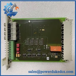
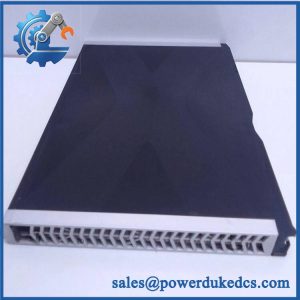
A failure in the central rack of a legacy H51q installation is not a simple card-level problem. The rack carries the central architecture itself: redundant processors, redundant safety buses, power distribution, monitoring, and the physical backplane that ties the system together. HIMA documentation identifies K 1412B as the central rack used for the H51q-HS/HRS system, with the H51q-HRS B5233-2 assembly using redundant buses and redundant central modules. The documented assembly is a 19-inch, 5U rack with three fan modules and associated rear-side protection and termination hardware.
For the H51q-HRS configuration, the assembly incorporates three F7126 power-supply modules rated 24 V/5 V, 10 A, one F7131 power-supply monitoring module, and two F8650X central modules. The B5233-2 arrangement uses four F7546 bus-termination modules for the redundant-bus architecture. HIMA documentation cited by current technical sources states that this H51q-HRS configuration is TÜV certified for applications up to SIL 3 according to IEC 61508. The important distinction is architectural: K1412B is the physical central rack, while H51q-HRS / B5233-2 / 997205233 identifies the specific redundant system assembly associated with that rack.
Module 4: Application Scenarios & Field Realities
- In an H51q safety cabinet supporting ESD or SIS functions, the K1412B is the structural center of the installation rather than an ordinary PLC chassis. The documented H51q-HRS assembly combines redundant central modules, redundant buses, triple power-feed capability, monitoring, and fan supervision in one controlled rack arrangement.
- During brownfield maintenance on a legacy HIQuad installation, the rack identifier matters as much as the processor model. A K1412B replacement should be matched to the original H51q-HRS configuration, because the B5233-2 assembly uses four F7546 termination modules for its redundant bus architecture; a single-bus H51q-HS arrangement is not the same hardware configuration.
- Where a shutdown has been traced to rack-level power or monitoring faults, inspect the complete assembly rather than replacing only the suspected CPU. The documented H51q-HRS package includes three F7126 power modules, one F7131 power monitoring module, fan modules, supply protection, and central modules. A failure in any of these interfaces can produce symptoms that resemble a processor fault.
- For an installed system with dual safety buses, verify the backplane and termination arrangement before changing hardware. Field identification of “K1412B” alone is insufficient because the same rack family can appear within different H51q system configurations. The H51q-HRS B5233-2 designation is the stronger configuration reference for a redundant-bus replacement.
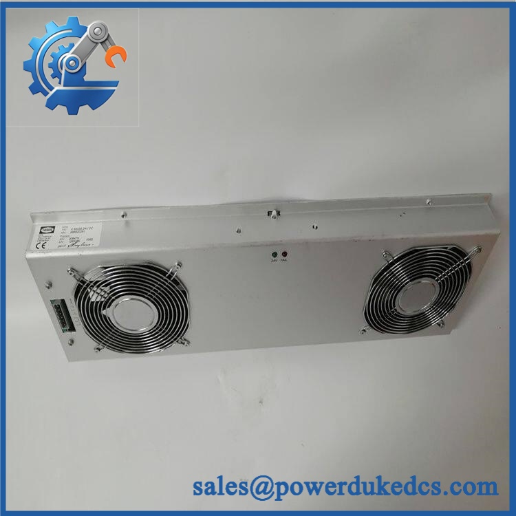
HIMA K1412B 996141261
Module 5: Migration, Compatibility & Installation Traps
Replacement Matrix
Exact K1412B / H51q-HRS / 997205233 configuration: Drop-in Replacement
When the replacement matches the installed rack assembly, rear-side components, bus architecture, power arrangement, and mechanical configuration, the rack can generally be exchanged without changing the application logic. The installed system documentation should still be used as the final authority.
with different H51q system configuration: Software Compatible / Hardware Configuration Verification Required
Do not substitute an H51q-HS single-bus configuration for an H51q-HRS redundant-bus configuration. The documented B5233-1 configuration uses one safety bus, while uses redundant buses.
Different HIMA rack generation: Hardware Modification Required
Do not assume mechanical fit, backplane compatibility, power architecture, or central-module compatibility across H41/H51 generations merely because the chassis is also a HIMA safety-system rack.
⚠️ Field Traps (Watch Out)
Redundant-bus mismatch: is specifically associated with the H51q-HRS redundant-bus system. HIMA documentation lists four F7546 bus-termination modules for , compared with two for B5233-1. Installing the wrong termination arrangement can compromise the intended bus architecture and should be treated as a configuration error, not a minor accessory difference.
Power and module completeness: The documented H51q-HRS assembly contains three F7126 24 V/5 V, 10 A power modules plus an F7131 monitoring module. A replacement rack received without the expected rear-side hardware or with a different power configuration is not automatically equivalent. Confirm the complete BOM against the cabinet drawings before energization.
Module 6: Quality Assurance SOP
Pre-Shipment QA Protocol for HIMA / H51q-HRS
- Step 1 — Identity Verification: Check the rack markings for , 996141261, H51q-HRS, , and 997205233. Record every visible identifier before testing.
- Step 2 — Configuration Verification: Confirm that the unit corresponds to the H51q-HRS redundant-bus arrangement rather than the H51q-HS single-bus version.
- Step 3 — OEM Anti-Counterfeit Visual Inspection: Inspect HIMA labels, chassis finish, backplane markings, terminal hardware, module labels, fasteners, and assembly workmanship for inconsistencies or signs of unauthorized modification.
- Step 4 — Mechanical Inspection: Check the 19-inch mounting flange, 5U chassis, card guides, backplane connectors, rear interfaces, cable routing provisions, and fan assemblies for deformation or damage.
- Step 5 — Power-System Verification: Confirm the presence and identification of the expected F7126 and F7131 modules where supplied as a complete H51q-HRS assembly. Check connectors and visible protection components before energization.
- Step 6 — Fan and Monitoring Check: Inspect the three documented fan modules and verify that fan-run monitoring circuitry is correctly connected and free of damaged wiring.
- Step 7 — Bus-Termination Verification: Confirm the expected four F7546 termination modules for the redundant-bus configuration.
- Step 8 — Power-On Self-Test: Under a controlled test setup, verify expected startup behavior, module status indications, power-rail stability, and absence of diagnostic faults.
- Step 9 — Communication and Central-Module Verification: Where the complete assembly is available for testing, verify synchronization and communication behavior of the redundant central modules and associated safety-bus interfaces.
- Step 10 — Final QC Record: Record model, all order codes, installed submodule identifiers, electrical configuration, visual condition, test results, and final QC disposition before packaging.
Configuration Control Note: Current technical documentation supports the identification of as the central rack associated with the HIMA H51q-HRS system, while / 997205233 denotes the redundant-bus assembly configuration. The documented assembly includes a 5U, 19-inch rack, three K9212 fan modules, three F7126 power modules, one F7131 monitoring module, two F8650X central modules, and four F7546 termination modules.



 Start Chat


