

Description
- Brand HIMA
- Full Model Number H7202
- System/Series Family HIMax Safety System
- Core Function Fused distribution of 24/48 VDC power to protected HIMax system branches
- Top 3 Hardcore Specs 24/48 VDC | 64 A maximum current | Distribution fuse board
- Stock Status New Surplus — verify revision, breaker/fuse configuration, and physical condition before shipment
Module 3: Technical Product Introduction
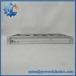
Power-distribution faults can propagate across multiple safety-system loads when branch protection is poorly separated. HIMA H7202 is a HIMax distribution fuse board designed to distribute and protect system power branches. HIMA approval documentation explicitly identifies H7202 as a Distribution Fuse Board, while FM certification specifies SELV/PELV operation for 24/48 VDC with a maximum current of 64 A.
The engineering distinction between H7202 and H7201 matters during replacement. H7201 is the feed-line and distribution fuse board with a higher documented maximum current of 92 A, while H7202 is the distribution-only board rated at 64 A. Neither should be selected solely from physical appearance. The associated circuit-breaker arrangement, power voltage, cabinet design, and approved HIMA configuration must match the original installation.
Module 4: Application Scenarios & Field Realities
- Within a HIMax safety-system cabinet, H7202 provides protected distribution of the incoming SELV/PELV supply to downstream circuits. The 64 A maximum rating establishes the upper distribution capacity; actual branch loading remains dependent on the installed protection devices and cabinet design.
- When several safety-system branches share one DC source, individual fuse or breaker protection helps localize a downstream electrical fault rather than allowing one branch problem to compromise every connected load. HIMA classifies specifically as a distribution fuse board, not as a controller or I/O module.
- During a HIMax cabinet rebuild, check whether the existing installation uses 24 VDC or 48 VDC distribution. FM documentation covers as a 24/48 VDC SELV/PELV distribution board with a 64 A maximum current, so supply-voltage compatibility must be established before energization.
- For maintenance in hazardous-area installations, the approval envelope also matters. HIMA’s current FM certificate identifies for Class I, Division 2, Groups A, B, C, and D applications with an ambient range of -20°C to +60°C and a T4A rating under the stated certification conditions.
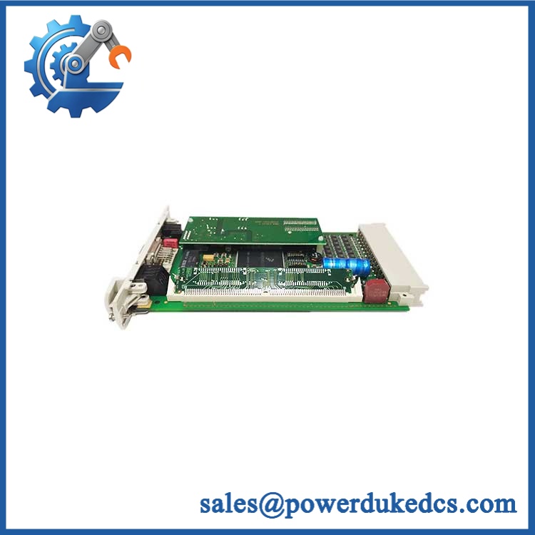
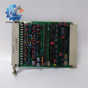
HIMA H7202
Module 5: Migration, Compatibility & Installation Traps
Replacement Matrix
| Replacement Status | Engineering Assessment |
|---|---|
| Drop-in Replacement | Yes, for an exact replacement installed in the same approved HIMax power-distribution arrangement with matching supply voltage and protection configuration. |
| Software Compatible | Not applicable. is a passive power-distribution and protection assembly with no user application firmware. |
| Hardware Modification Required | Normally no for an exact replacement. Hardware changes may be required when changing voltage architecture, breaker/fuse configuration, cabinet wiring, or the associated distribution assembly. |
⚠️ Field Traps: Watch Out
Do not substitute H7201 for simply because both are distribution boards. HIMA documentation distinguishes the two: H7201 is the feed-line and distribution fuse board rated up to 92 A, while is the distribution fuse board rated up to 64 A. Their electrical role and current capability are not identical.
Verify the system voltage before connecting the board. is approved for 24/48 VDC SELV/PELV distribution. A cabinet configured for one voltage should not be treated as interchangeable with another merely because the physical board is the same.
Branch protection must match the actual load. The 64 A figure is the board’s documented maximum current rating, not the allowable current for every individual outgoing circuit. Check each fitted circuit breaker or fuse against conductor sizing, load current, and the approved HIMA cabinet design.
Do not bypass a tripped protective device. A repeated trip is evidence of a downstream electrical problem. Bridging a fuse or installing a higher-rated protective device can defeat the intended fault-isolation scheme.
Module 6: Quality Assurance SOP
is a power-protection component, so pre-shipment verification should concentrate on electrical integrity, protective-device configuration, and mechanical condition.
- OEM anti-counterfeit visual inspection: Verify HIMA identification, exact designation, visible revision markings, board construction, terminal arrangement, protective-device interfaces, and manufacturer markings against controlled references.
- Part-number and traceability check: Record model, revision, serial/date code, and all available manufacturing identifiers.
- Mechanical inspection: Examine terminals, mounting points, insulating barriers, fuse or circuit-breaker holders, connector interfaces, and accessible hardware for cracking, discoloration, corrosion, contamination, or evidence of overheating.
- Protection-device verification: Record the installed fuse or circuit-breaker type and rating for every populated branch. Do not assume the same configuration applies to every installation.
- Continuity test: With the unit completely de-energized, verify the intended DC distribution paths and protective-device continuity.
- Polarity verification: Confirm correct positive/negative routing before any powered test.
- Insulation verification: Check for unintended continuity between separated conductive sections according to the applicable HIMA test procedure.
- 24/48 VDC controlled energization: Apply the correct verified supply voltage using a current-limited laboratory setup and monitor branch voltage distribution for abnormal drops or heating.
- Load test: Exercise representative protected branches using controlled loads while staying within the documented 64 A maximum board rating and the installed branch-protection limits.
- Protection-response test: Where the approved fixture permits, confirm expected protective-device behavior with a controlled current source rather than an uncontrolled short circuit.
- Thermal inspection: Monitor terminal and protection-device temperatures during an extended representative load test, looking for abnormal temperature rise or high-resistance connections.
- System-level verification: After installation, verify that the connected HIMax power branches receive the intended DC voltage and that no cabinet-level supply or protection diagnostics are generated.
- Communication handshake verification: Not applicable to itself. Acceptance should be based on correct power distribution and successful operation of the connected HIMax hardware.
- Final QC record: Document exact model and revision, supply voltage tested, protective-device configuration, continuity results, load-test measurements, thermal observations, traceability, and packing status.
Technical Identification Note: HIMA’s certification records identify as a HIMax Distribution Fuse Board. The official FM documentation specifies 24/48 VDC SELV/PELV operation with a 64 A maximum current, while HIMA’s approval records distinguish it from H7201, the higher-current feed-line and distribution fuse board.



 Start Chat


