

Description
- Brand Triconex / Invensys
- Full Model Number DO3401 / Model 3401
- System/Series Family Trident Safety Instrumented System
- Core Function TMR 16-point commoned digital output interface for 24 VDC field loads
- Top 3 Hardcore Specs 16 output points | 24 VDC nominal | 15–30 VDC operating range
- Stock Status New Surplus — verify hardware revision, baseplate, termination configuration, and field-load requirements before shipment
Module 3: Technical Product Introduction
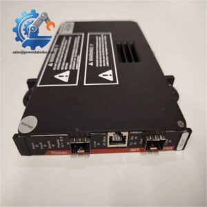
A digital output failure becomes serious when the affected channel drives a shutdown solenoid, valve actuator, relay, or other final element. Triconex DO3401 / Model 3401 is the Trident Digital Output Module, providing 16 commoned output points at a nominal 24 VDC. The module uses three isolated channels that independently receive output commands from the corresponding main processors, with the Trident architecture applying redundant output selection before the field circuit is driven. The module also supports hot sparing for online replacement of a faulty output module.
The electrical limits are important during replacement. The documented operating range is 15–30 VDC, with 33 VDC specified as the absolute maximum output voltage. Switching current is self-limited to less than 4.8 A, with 3 A typical, while continuous carry current is self-limited above 0.7 A and typically 1.5 A. Loop-back monitoring distinguishes 0–5 VDC as Off, 6–14 VDC as a transition region, and 15–30 VDC as On; all 16 output points can be scanned in less than 1 ms.
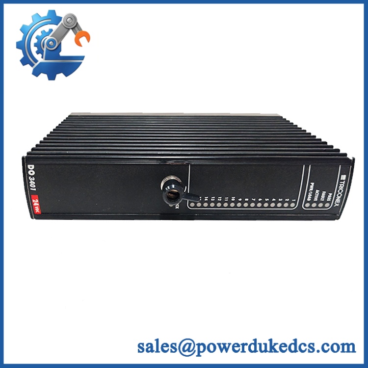
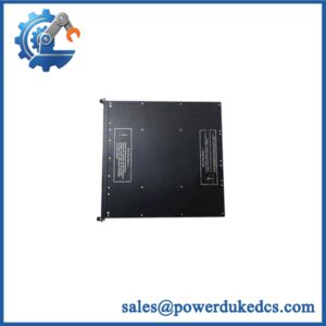
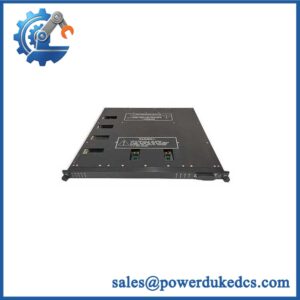
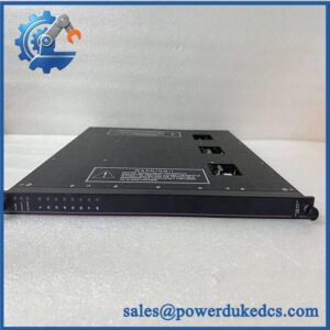
Triconex DO3401
Module 4: Application Scenarios & Field Realities
- At an emergency shutdown cabinet, DO3401 can drive 24 VDC field devices such as shutdown solenoids, interposing relays, and discrete actuators. The 16-point commoned arrangement is intended for installations where several outputs share the same field-power architecture.
- When a solenoid circuit repeatedly reports an output fault, test the field load and suppression components before replacing the module. The documented output circuitry includes self-limiting current behavior and loop-back detection, so an external short or abnormal load can appear as an output-module fault.
- For applications requiring online maintenance, the Trident DO architecture supports hot sparing. A prepared spare can be installed according to the approved maintenance procedure while the active module remains part of the operating system. Do not interpret hot-sparing capability as permission to remove a module without confirming the controller’s actual maintenance state.
- During final-element troubleshooting, the loop-back thresholds are useful diagnostic references. A measured output that falls into the 6–14 VDC transition region should not immediately be interpreted as a logic-command problem; check load resistance, field power, terminals, and output wiring first.
Module 5: Migration, Compatibility & Installation Traps
Replacement Matrix
| Replacement Status | Engineering Assessment |
|---|---|
| Drop-in Replacement | Yes, for a like-for-like DO3401 / Model 3401 installation using the correct Trident baseplate and approved field termination arrangement. |
| Software Compatible | Generally yes for an exact module replacement, but the Trident configuration, output assignments, diagnostic parameters, and approved controller revision must be verified. |
| Hardware Modification Required | Normally no for an exact DO3401 replacement. Hardware changes may be required when changing output voltage class, baseplate type, termination architecture, or module family. |
⚠️ Field Traps: Watch Out
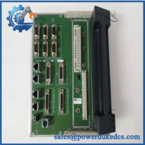
Verify the baseplate before inserting the replacement. Trident documentation associates Model 3401 with the 2401 Digital Output Baseplate Kit; the low-current TriPak configuration also uses a 3401 module with a 2401L baseplate. The module and baseplate should therefore be treated as a matched installation set.
Do not treat 3 A as the normal continuous load for every channel. The documented figure separates switching current from carry current: switching is self-limited to less than 4.8 A, with 3 A typical, while carry current is typically 1.5 A. The actual permissible load depends on the field circuit and thermal conditions.
Check the commoned-output architecture. Model 3401 has 16 commoned points, so field-power routing and common/reference wiring must match the approved baseplate schematic. One wiring error can affect multiple apparently unrelated output diagnostics.
Pay attention to inductive loads. Solenoids and contactors can generate switching transients. Confirm the approved suppression arrangement and actual load characteristics before testing the replacement under production conditions.
Do not substitute a high-voltage output module by physical similarity. The Trident product guide separates the standard 3401 digital output module from the 5402 high-voltage TriPak arrangement. The standard 3401 specification is based on a 24 VDC output architecture.
Module 6: Quality Assurance SOP
A surplus DO3401 should be tested channel-by-channel in a controlled Trident-compatible fixture. Power-up alone is not adequate evidence for a safety-system output module.
- OEM anti-counterfeit visual inspection: Verify Triconex/Invensys identification, / Model 3401 marking, PCB revision, connector geometry, front-panel indicators, and manufacturing identifiers against controlled references.
- Part-number and traceability check: Record exact model, hardware revision, serial number, date code, and associated baseplate/termination information.
- Mechanical inspection: Examine the backplane connector, enclosure, locking/keying mechanism, PCB, output interface, and mounting hardware for bent contacts, corrosion, contamination, cracks, or unauthorized rework.
- Power-on self-test (POST): Install the module in an approved Trident test arrangement and verify expected PASS, FAULT, ACTIVE, and PWR/LOAD indications. The published front-panel arrangement identifies these status functions.
- 24 VDC supply verification: Apply a controlled field supply within the documented 15–30 VDC operating range and monitor supply stability and module current.
- 16-channel output test: Exercise all 16 outputs independently with calibrated test loads and verify correct On/Off transitions.
- Output-threshold verification: Confirm representative Off, transition, and On states against the documented loop-back thresholds of 0–5 VDC Off, 6–14 VDC transition, and 15–30 VDC On.
- Load-current test: Test representative outputs under controlled resistive loads while staying within the documented switching and carry-current limits.
- Short-circuit protection test: Where the approved laboratory fixture permits, use a current-limited fault simulation to verify protective behavior. Do not apply uncontrolled hard shorts to a safety module.
- Leakage verification: Measure Off-state leakage under the prescribed test conditions; the documented leakage to load is less than 1 mA.
- Loop-back diagnostic test: Exercise the documented output loop-back function and confirm that output-state discrepancies or field faults are detected as expected.
- Diagnostic timing test: Where the test fixture supports dynamic measurement, verify the documented loop-back scan behavior of less than 1 ms for all 16 points and diagnostic glitch duration below the specified limit.
- Isolation verification: Test functional-to-protective-earth isolation and functional-to-functional-earth isolation using the approved laboratory procedure; the documented minimum values are 500 VDC and 800 VDC, respectively.
- Hot-spare verification: Confirm the module can be recognized and configured as the spare unit in the approved Trident test environment.
- System recognition test: Verify correct module identification, output addressing, diagnostics, and data exchange through the Trident I/O bus.
- Communication handshake verification: Confirm successful module-to-main-processor data exchange and correct three-channel output-command reporting. The itself is an I/O module, not a standalone Ethernet or Modbus interface.
- Field-load simulation: Test representative solenoid or relay loads where the laboratory fixture permits, including the applicable suppression network.
- Extended-run test: Operate representative outputs continuously while monitoring output stability, diagnostic events, supply current, connector temperature, and intermittent faults.
- Final QC record: Document hardware revision, all 16 output results, voltage and current measurements, leakage, loop-back diagnostics, isolation results, hot-spare recognition, system diagnostics, extended-run observations, traceability, and packaging condition.
Technical Identification Note: Trident documentation identifies / Model 3401 as a 16-point, commoned digital output module with a 24 VDC nominal output, 15–30 VDC operating range, self-limiting switching current, loop-back diagnostics, and sub-1-ms scanning of all 16 points. The Trident product guide also associates the 3401 with the 2401 digital-output baseplate. Secondary listings sometimes publish incorrect point counts or high-voltage specifications, so the controlled Trident documentation should govern procurement and replacement decisions.



 Start Chat


