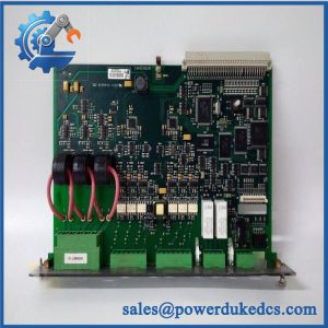
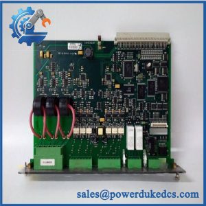
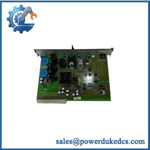
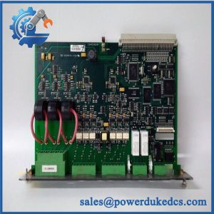
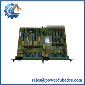
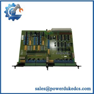
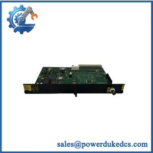
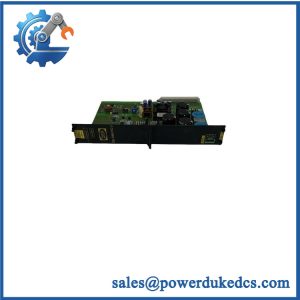
Description
-
Brand: DEIF
-
Full Model Number: PBC-2
-
DEIF Ordering Number: 1240040001
-
Lifecycle Status: Legacy specialist equipment; current production status requires confirmation
-
Core Function: High-voltage pitch battery charging and maintenance for wind turbine pitch-control systems
-
Top 3 Technical Specs:
-
AC Input: 185–230 VAC, 40–70 Hz
-
DC Output: 330 VDC nominal, 1.8 A
-
Temperature Control: Automatic output-voltage adjustment from −25°C to +65°C using a PT100 sensor
-
-
Additional Specifications: 370 VDC output overvoltage protection; alarm relay; short-circuit protection; reverse-polarity protection
-
Mounting: Chassis mount
-
Dimensions: 109 × 270 × 181 mm (W × H × D)
-
Weight: 2.80 kg
-
Stock & Condition: Confirmed at quotation stage; unit identification, physical condition, inspection scope, and dispatch schedule documented before order release
Obsolescence & Supply Chain Deep Dive
A failed pitch battery charger can compromise the readiness of a wind turbine’s pitch-control system. The DEIF PBC-2 is designed to charge and maintain the battery or ultracapacitor arrangement used in pitch applications. Its nominal output is 330 VDC at 1.8 A, with temperature-controlled output adjustment for the specified operating range. The unit also provides voltage monitoring and an alarm relay for battery-condition supervision. When sourcing this specialist component, verify DEIF ordering number 1240040001, rather than relying on the PBC-2 model designation alone. Current factory-production status and new-unit availability should be confirmed before procurement (factory-new lead times may differ from the dispatch schedule for an inspected spare).
For wind-farm maintenance teams, replacing a failed charger with a verified matching unit can avoid the engineering cost of immediately redesigning an existing pitch-control cabinet. Keeping the original system architecture may reduce wiring changes, commissioning hours, and turbine downtime. The total cost of ownership should include the spare unit, technician labor, electrical safety checks, and verification of the battery-monitoring circuit. A low purchase price offers limited value if the output characteristics, temperature compensation, or alarm thresholds differ from the installed equipment. Where the existing design remains serviceable, retaining a compatible spare may be the more economical short-term maintenance strategy.
Compatibility & Replacement Matrix
The DEIF PBC-2 is a specialist high-voltage pitch battery charger, not a conventional 24 VDC control-cabinet power supply. Check the electrical ratings and installed configuration before authorizing a replacement.
|
Replacement Scenario |
Classification |
Preliminary Labor and Cost Planning |
|---|---|---|
|
Identical PBC-2, ordering number 1240040001, with matching application and terminal configuration |
Conditional drop-in replacement |
Approximately 2–4 technician hours; labor cost calculated using the site’s hourly rate |
|
Same PBC family but a different output-voltage variant |
Engineering review required; not automatically interchangeable |
Approximately 4–8 hours for evaluation and testing, excluding any additional redesign |
|
Different charger model or incompatible output, monitoring, or temperature-control arrangement |
Hardware modification or engineered migration |
Approximately 8–24+ engineering and technician hours, depending on cabinet changes and commissioning requirements |
These figures are preliminary planning allowances, not manufacturer quotations or guaranteed installation times. Total cost also depends on replacement-part pricing, access to the turbine, safety procedures, and site commissioning requirements.
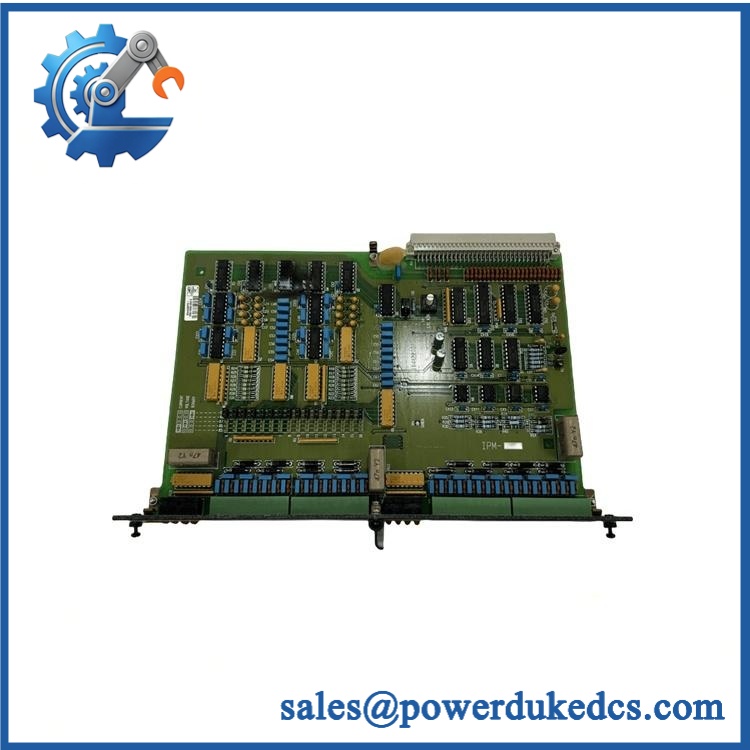
DEIF PBC-2
Field Traps to Check Before Ordering
Output-voltage mismatch
The PBC family includes multiple variants with different output ratings. The PBC-2 has a nominal 330 VDC output and a rated output current of 1.8 A. Other variants use different voltage and current ratings. Do not substitute a PBC-300-2, PBC-360-2, or another variant solely because its housing or terminal layout appears similar.
Temperature sensor and insulation requirements
The supports temperature-controlled output adjustment using a three-wire PT100 sensor. The X4 temperature-sensor connection is not galvanically isolated from the X5 output. DEIF specifies double-insulated shielded wiring with a minimum 4,000 V test rating for this connection. An incorrect sensor connection or unsuitable cable insulation can create an electrical safety hazard.
Alarm and battery-check configuration
The alarm relay activates when the monitored output voltage reaches or exceeds 295 VDC. The X3 battery-check input accepts a 12–30 VDC control signal and reduces the output voltage by approximately 10% when activated. Confirm the wiring and control logic against the installed system documentation before commissioning.
Quality Assurance & Testing SOP
Each allocated DEIF should undergo documented inspection and appropriate functional testing before shipment. Testing must distinguish between visual verification, bench-tested operation, and complete application-level validation.
Visual Inspection and Manufacturer Identification
-
Conduct an OEM anti-counterfeit visual inspection of the DEIF nameplate, model designation, serial information, and ordering number.
-
Compare the identification label with the supplied purchase specification and available manufacturer documentation.
-
Inspect the metal housing, terminal blocks X1–X5, fixing points, and electrical insulation barriers.
-
Check for corrosion, heat damage, contamination, cracked connectors, unauthorized repairs, or altered markings.
-
Record the physical condition and photograph the unit before packing.
Power-On and Electrical Verification
-
Connect the unit to a protected test supply within its specified 185–230 VAC input range and 40–70 Hz frequency range.
-
Use the specified external protective device: a 10 A time-delay fuse or 10 A D-characteristic miniature circuit breaker, as applicable to the installation.
-
Verify startup behavior and the power-status indication.
-
Measure the DC output with appropriately rated instruments and compare it with the expected temperature-dependent output.
-
Confirm that the charger delivers its rated output current of 1.8 A under a suitable controlled load.
-
Inspect the output for abnormal fluctuations, unexpected shutdowns, or visible signs of overheating.
Safety requirement: The DC output can reach hazardous voltage levels. Testing must be performed by qualified personnel using appropriate high-voltage test equipment, barriers, and isolation procedures.
Monitoring, Temperature Control, and Protection Checks
-
Verify the alarm relay operation and confirm the applicable voltage-monitoring threshold.
-
Check the X3 battery-check response using the specified control-signal range.
-
Where the test setup permits, verify the X4 PT100 temperature-control response across an appropriate temperature range.
-
Inspect the output response under controlled load conditions.
-
Record any unavailable tests instead of representing them as passed.
-
Confirm that the unit has no unresolved test failures before approving shipment.
Final Inspection and Shipping Records
-
Record the model, ordering number, serial information, inspection date, and test results.
-
Include the applicable functional-test report when specified in the purchase agreement.
-
Package the charger to protect its terminals, housing, and electrical insulation against transport damage.
-
Use suitable protective packaging and handling labels for electrical equipment.
-
Retain inspection photographs and the final dispatch record.
Bench testing does not replace turbine-level commissioning. The maintenance team must verify the charger, battery or ultracapacitor arrangement, alarm logic, and temperature compensation within the actual pitch-control system before returning it to service.
Procurement & Lifecycle FAQ
Is the DEIF in stock, and what is the emergency shipping cutoff?
Stock availability and dispatch timing depend on the specific unit and order requirements. Confirm the model, ordering number 1240040001, condition, test scope, and quantity when requesting a quotation. Emergency dispatch must account for payment clearance, inspection requirements, packing, and the carrier’s collection cutoff. Obtain a written dispatch commitment before arranging urgent maintenance work.
How do you verify the authenticity and condition of obsolete or surplus DEIF units?
The verification process should include a visual inspection of manufacturer markings, ordering number, serial information, terminal layout, and housing condition. Functional testing should cover the output voltage, controlled-load operation, status indication, and applicable monitoring functions. Request current unit photographs and available test records before issuing the purchase order. Visual inspection alone cannot establish full electrical functionality.
Are there electrical compatibility issues my engineers should review before issuing the purchase order?
Yes. Confirm the 185–230 VAC input, 330 VDC nominal output, 1.8 A rated current, temperature-control arrangement, and alarm-relay wiring. The PT100 interface and high-voltage output also require particular attention to insulation and wiring specifications. Engineers should compare the installed unit’s identification and circuit diagrams with the proposed replacement before authorizing installation.
What warranty and return terms apply to the DEIF ?
Warranty coverage and return eligibility should be stated in writing on the quotation or pro forma invoice. Confirm the warranty period, exclusions, claim procedure, and return authorization requirements before purchasing. New, surplus, and previously used units may have different coverage terms. Do not assume that all conditions carry the same warranty.
Should we buy a replacement or upgrade the pitch-control power system?
For an otherwise serviceable turbine, a verified replacement charger may offer a lower immediate maintenance cost than a broader system redesign. An upgrade may be justified when the existing equipment has repeated failures, limited spare availability, or electrical requirements that can no longer be met. Compare the purchase cost, engineering labor, cabinet modifications, commissioning effort, and expected downtime before approving the investment.