Description
-
Brand: DEIF
-
Full Model Number: TAC-311DG
-
Product Type: Single-function AC current transducer
-
Lifecycle Status: Phased out by DEIF; the manufacturer currently lists no direct replacement
-
Core Function: Converts a measured single-phase AC current into a proportional DC current or voltage signal for PLCs, monitoring instruments, indicators, and alarm systems
-
Top 3 Technical Specs: Class 0.5 measurement accuracy; 45–65 Hz continuous frequency range; 55 × 75 mm compact design
-
Measurement Range: Variant-dependent, with nominal input options including 1 A, 1.3 A, 5 A, and 6.5 A AC
-
Output Options: Variant-dependent DC current or voltage output; 4–20 mA is one documented configuration
-
Auxiliary Supply: Available configurations include 24 V DC, 48–110 V DC, 88–220 V DC, and 110/230/440 V AC
-
Mounting: 35 mm DIN rail or base mounting
-
Stock & Condition: Available quantity, exact variant, condition, test status, and dispatch date require confirmation
Obsolescence & Supply Chain Deep Dive
A failed current transducer can interrupt feedback to a PLC, monitoring instrument, or alarm system even when the primary electrical equipment remains operational. The DEIF TAC-311DG measures single-phase AC current and converts it into a proportional DC output for downstream control and monitoring equipment. Its phased-out status creates a sourcing challenge for facilities maintaining older switchboards and generator control panels. Crucially, TAC-311DG units were supplied in different measurement-range, output, and auxiliary-supply configurations. Confirm the complete installed specification before purchasing; the model number alone does not identify every electrical variant.
Replacing a failed transducer can preserve existing control wiring and monitoring equipment without redesigning the entire measurement circuit. The total cost of ownership (TCO) calculation should include the replacement price, installation labor, calibration checks, signal verification, and downtime exposure. For preliminary planning, allow approximately 1–2 maintenance labor hours for a straightforward replacement and signal check, excluding fault diagnosis and additional commissioning. This is a planning allowance, not a guaranteed completion time. Because DEIF currently lists no direct replacement, retain a verified spare where the measurement loop is operationally critical. If an alternative transducer is considered, compare its input range, output scaling, supply requirements, response time, and isolation characteristics before approving the substitution.
Compatibility & Replacement Matrix
|
Replacement Scenario |
Classification |
Required Action |
Preliminary Time Allowance |
|---|---|---|---|
|
Exact TAC-311DG variant with matching input, output, and supply |
Conditional drop-in replacement |
Verify the complete part reference, measuring range, output signal, auxiliary supply, and terminal assignment. |
1–2 maintenance labor hours |
|
TAC-311DG with a different measurement or output variant |
Engineering verification required |
Compare current range, output scaling, auxiliary supply, wiring, and receiving-device settings. |
1–2 engineering hours for initial review |
|
Modern DEIF TAS-series transducer proposed as an alternative |
Not an automatic replacement |
Assess configuration, electrical interfaces, output scaling, mounting, and installation requirements. |
Estimate after technical review |
|
Alternative transducer requiring different wiring or signal scaling |
Hardware or configuration modification may be required |
Review panel drawings, receiving-device input characteristics, signal calibration, and commissioning requirements. |
Site-specific estimate required |
Cost planning: Calculate the installed replacement cost using the quoted transducer price, maintenance labor, calibration work, and any required panel modifications. A modern substitute may reduce future sourcing risk but increase initial engineering costs. Final estimates depend on the existing measurement loop and the proposed replacement’s configuration.
Field Traps to Check Before Ordering
-
Measurement-range mismatch: TAC-311DG variants are available for different nominal AC current ranges. Confirm the installed input specification and current-transformer secondary rating before selection.
-
Output signal mismatch: Verify whether the receiving device expects 4–20 mA, another DC current range, or a voltage signal. Confirm output scaling and the zero and span settings where applicable.
-
Auxiliary supply mismatch: The requires an auxiliary supply. Match the installed supply to the exact replacement variant; do not assume that every unit accepts both AC and DC power.
-
Load and response requirements: Check the receiving input’s load or burden requirements and the required signal response time. The documented response time is below 300 ms under specified test conditions.
-
Electrical isolation: The published specifications include galvanic separation between the input, output, and auxiliary supply. Confirm that any proposed replacement meets the installation’s isolation requirements.
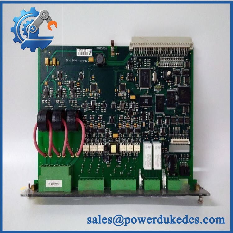
DEIF TAC-311DG
Quality Assurance & Testing SOP
The following procedure defines a proposed inspection and pre-shipment test scope for DEIF inventory. Test conditions must match the exact transducer variant and applicable technical documentation.
Visual Inspection and Traceability
-
Part-number verification: Record the designation, complete available part reference, auxiliary supply rating, and measuring-range identification.
-
Physical examination: Inspect the enclosure, terminals, mounting features, and accessible surfaces for corrosion, contamination, impact damage, or unauthorized rework.
-
Authenticity screening: Review manufacturer markings, label consistency, available production details, and traceability records.
-
Condition declaration: Identify the actual unit as new original, new surplus, or previously used, as applicable.
-
Photographic evidence: Photograph the actual transducer, nameplate, terminal arrangement, and visible ratings before packaging.
Power-On and Electrical Checks
-
Verify the auxiliary supply rating and polarity, where applicable, before energization.
-
Use an appropriate protected test setup and calibrated measurement instruments.
-
Confirm that the unit powers up under the specified conditions without abnormal heating, odor, or visible damage.
-
Verify the applicable output signal and output limits against the technical specification for the exact variant.
-
Record the supply voltage, measured output, test conditions, and observed abnormalities.
Current Measurement and Output Testing
-
Input simulation: Apply controlled AC current signals within the specified measuring range using suitable calibrated equipment.
-
Zero and span verification: Check the specified lower and upper measurement points and confirm the proportional output response.
-
Accuracy assessment: Compare the measured output with the reference input at appropriate test points. Document deviations against the applicable Class 0.5 acceptance criteria.
-
Output loading: Test with a load appropriate to the selected output type and within the manufacturer’s permitted limits.
-
Frequency response: Verify operation within the documented 45–65 Hz continuous range.
-
Overload requirements: Do not conduct overload testing unless the approved test procedure specifically requires it and suitable protective equipment is available.
Final Acceptance and Shipment Release
-
Match the tested unit’s identification and electrical variant against the purchase order.
-
Record the actual measurement results, test equipment, and acceptance criteria.
-
Provide the agreed inspection report and actual-unit photographs.
-
Identify any tests not performed; do not describe inspection-only stock as fully function-tested.
-
Package the transducer with appropriate mechanical and electrostatic-discharge protection for its handling requirements.
-
Release the unit only after the agreed acceptance criteria have been met.
Testing limitation: Bench verification of the does not establish the accuracy of the entire installed measurement loop. Final acceptance should include wiring checks, receiving-device scaling, signal verification, and any required calibration procedures.
Procurement & Lifecycle FAQ
Is the DEIF in stock, and what is the emergency shipping cutoff?
The is phased out, so availability depends on existing inventory. Request written confirmation of the exact variant, available quantity, condition, test status, and dispatch date. Emergency shipment depends on warehouse readiness, payment clearance, export documentation, and carrier collection schedules. Same-day dispatch should not be assumed without confirmation.
How do you verify authenticity and condition for this discontinued transducer?
Request photographs of the actual unit, identification label, electrical ratings, and available traceability information. Obtain a written condition declaration and agree on the pre-shipment testing scope. For a tested unit, request documented measurements covering the input range, output response, and auxiliary supply. Visual inspection alone cannot establish measurement accuracy.
Are there compatibility issues when replacing the ?
The main risks concern the measuring-current range, output signal, auxiliary supply, and receiving-device scaling. Confirm all four against the installed unit and the panel drawings before issuing the purchase order. A similar model designation does not establish electrical interchangeability.
What warranty and return terms should be confirmed before purchasing?
Confirm the warranty period, commencement date, defect coverage, exclusions, and return authorization procedure in writing. Establish the deadline for reporting a defective-on-arrival unit and responsibility for return freight. For surplus equipment, clarify whether the warranty covers functional failure and whether the supplier requires a test report or installation evidence to process a claim.
Is there a direct replacement for the DEIF ?
DEIF currently lists no direct replacement for the . Its TAS-series transducers provide alternative measurement functions, but they must not be treated as automatic substitutes. An engineer should compare the current input range, output signal, auxiliary supply, measurement accuracy, isolation, and wiring requirements before selecting an alternative. For critical measurement loops, retaining a verified spare may provide the lowest-disruption interim solution while a longer-term migration is evaluated.