Description
- Brand: Foxboro
- Full Model Number: 870ITEC-AYFNZ-7
- System / Series Family: Foxboro I/A Series Intelligent Transmitters
- Core Function: Intelligent electrochemical transmitter for electrodeless conductivity measurement, converting sensor measurements into a 4–20 mA analog output.
- Top 3 Technical Specs: 12.5–42 VDC supply; 1 W maximum power consumption; 4–20 mA analog output.
- Sensor Compatibility: Foxboro 871EC series electrodeless conductivity sensors and 871FT series flow-through sensors; other electrically compatible sensors require suitable configuration.
- Maximum Sensor Cable Length: 30.5 m (100 ft)
- Ambient Operating Temperature: -25°C to +55°C
- Temperature Compensation Inputs: 100 Ω platinum RTD, 1,000 Ω platinum RTD, or 100 kΩ thermistor, subject to configuration.
- Model Configuration: Analog-only output; pipe mounting for a nominal 2-inch or DN 50 pipe; FNZ nonincendive electrical classification; optional storm door.
- Lifecycle Status: Listed as discontinued in supplier records; confirm current OEM support and availability.
- Stock Status: Actual quantity, condition, calibration details, and dispatch readiness require confirmation.
Commercial-Technical Deep Dive
When conductivity monitoring fails in a chemical processing, water treatment, or utility application, operators can lose visibility into a process variable that directly affects product quality and process control. The Foxboro 870ITEC-AYFNZ-7 is an intelligent electrochemical transmitter designed for electrodeless conductivity measurement. It accepts compatible conductivity sensor inputs and produces a 4–20 mA output for an appropriate receiving instrument or control system. Its analog-only configuration is important: the model code does not specify digital communications, so do not purchase this version when the application depends on a digital field-device interface. The Y mounting code identifies a pipe-mounted configuration, while the -7 option denotes a storm door. Confirm the complete model designation and electrical classification on the installed unit before ordering.
With a 12.5–42 VDC supply range and maximum power consumption of 1 W, the transmitter can support an existing two-wire analog measurement loop without requiring a separate high-power transmitter supply. Its sensor connection supports a maximum separation of 30.5 m under the documented installation conditions. Temperature compensation can accommodate specified platinum RTDs or a thermistor, depending on the configured application. These features may help preserve existing measurement wiring and downstream control logic when a like-for-like replacement is selected. From a total cost of ownership (TCO) perspective, compare the replacement price with the costs of recalibration, loop testing, process downtime, and a potential migration to another analyzer platform. The actual conductivity range depends on the sensor, cell factor, and transmitter configuration; verify these parameters before approving the replacement.
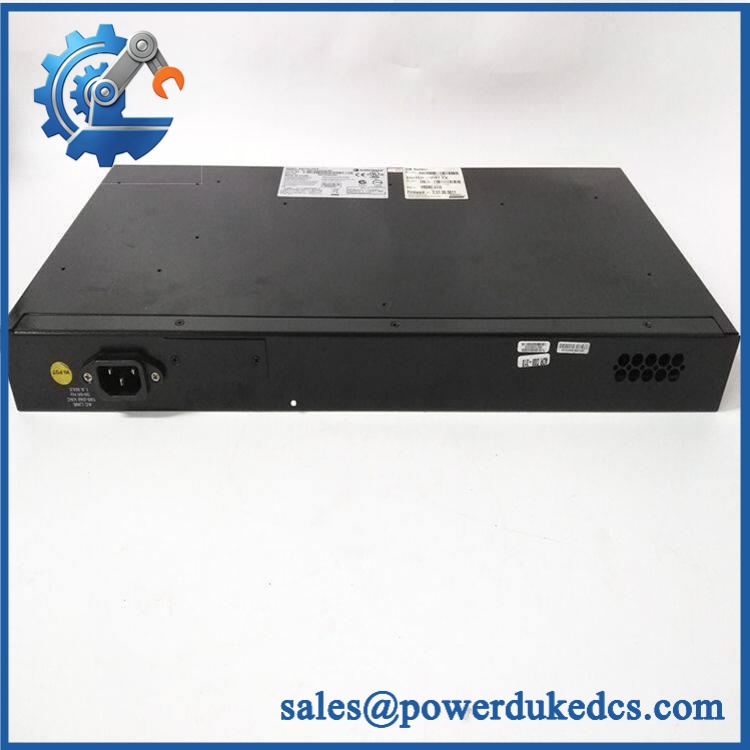
Foxboro 870ITEC-AYFNZ-7
Compatibility & Installation Traps
Migration and Compatibility
| Replacement Scenario | Classification | Required Action | Preliminary Time Allowance |
|---|---|---|---|
| Exact 870ITEC-AYFNZ-7 replacement | Conditional drop-in replacement | Match the complete model code, mounting arrangement, sensor type, supply, output loop, and electrical classification. | 1–2 maintenance labor hours |
| Same 870ITEC family with a different model code | Engineering verification required | Compare output options, mounting, certification, and configuration requirements. | 1–2 engineering hours for initial review |
| Alternative Foxboro conductivity transmitter | Not an automatic replacement | Verify sensor compatibility, measurement range, loop requirements, mounting, and output behavior. | Estimate after technical review |
| Transmitter with digital communications instead of analog-only output | Configuration or system changes may be required | Check the receiving system, communication requirements, scaling, and loop wiring before selecting an alternative. | Site-specific estimate required |
Replacement guidance: An exact model replacement does not automatically require a firmware flash or logic rewrite. However, sensor calibration, conductivity range, temperature compensation, and analog scaling must be checked before returning the measurement loop to service.
Field Traps to Check Before Ordering
- Sensor incompatibility: The 870ITEC is intended for compatible electrodeless conductivity sensors, including the 871EC and 871FT families. A contacting conductivity sensor is not an automatic substitute. Verify sensor type and cell factor before connecting the replacement.
- Output load and loop supply: The 4–20 mA output must operate within the documented load limits at the actual supply voltage. Check loop resistance, receiving-device input impedance, and any connected configurator before energizing the transmitter.
- Hazardous-area classification: The FNZ model code is associated with a nonincendive classification for specified hazardous locations. Confirm the exact nameplate marking, temperature class, installation method, and applicable site requirements; do not assume suitability for every hazardous area.
- Calibration retention: Do not assume that the replacement preserves the original measurement range or sensor calibration. Record the existing cell factor, range, temperature compensation settings, and output scaling before removal where the approved procedure permits.
Power-down and removal: Do not assume that this transmitter supports hot swapping. Follow the site’s approved process isolation, electrical safety, and loop maintenance procedures. If the analog signal participates in an alarm, interlock, or control function, assess the consequences of signal loss before disconnecting the transmitter.
Quality Assurance SOP
The following procedure defines the proposed pre-shipment inspection and acceptance scope for Foxboro 870ITEC-AYFNZ-7 inventory. Testing should follow the applicable product documentation and use suitable calibrated equipment. Actual test results must be distinguished from checks that were not performed.
Visual Inspection and Product Authentication
- OEM anti-counterfeit visual inspection: Examine the manufacturer label, model designation, serial or production information, and available traceability records.
- Part-number verification: Confirm the complete 870ITEC-AYFNZ-7 designation rather than relying on the 870ITEC prefix alone.
- Enclosure inspection: Check the housing, cable entries, terminals, mounting features, and storm-door assembly for corrosion, impact damage, contamination, or missing components.
- Configuration verification: Record the electrical classification, mounting option, and visible identification details.
- Condition declaration: Identify the actual unit as new original, new surplus, or previously used, as applicable.
- Photographic documentation: Capture the actual unit, complete nameplate, mounting configuration, and available accessories.
Power-On and Electrical Testing
- Verify the supply range against the nameplate and applicable documentation before energization.
- Use a controlled test setup with suitable current measurement and circuit protection.
- Confirm that the transmitter powers up without abnormal heating or visible fault conditions.
- Measure the analog output under suitable reference conditions and compare it with the expected response.
- Check status indicators or diagnostic information only where those features are fitted and documented for the specific unit.
- Record the input supply voltage, output current, test conditions, and observed results.
Conductivity Measurement and Loop Verification
- Sensor compatibility: Connect a suitable electrodeless conductivity sensor or an approved sensor simulator appropriate to the test procedure.
- Range verification: Check the configured measurement range and cell factor against the agreed application specification.
- Analog output testing: Verify representative points across the intended measurement range and confirm that the 4–20 mA output follows the expected scaling.
- Temperature compensation: Where required, verify the selected RTD or thermistor input and associated configuration.
- Loop load testing: Confirm that the transmitter operates within the documented supply and output-load limits.
- Receiving-system verification: Where the setup permits, connect the output to a suitable loop receiver and check displayed values against the reference.
- Test reporting: Record reference values, measured output, deviations, and acceptance criteria.
Communication test limitation: The AYFNZ model code specifies an analog-only output configuration. A digital communication handshake test is therefore not applicable to this version unless separate, documented communication functionality is identified.
Final Acceptance and Shipment Release
- Reconcile the tested model number and visible configuration with the purchase order.
- Provide actual-unit photographs and the agreed inspection and test records.
- Clearly identify whether the unit received visual inspection, electrical testing, or full measurement-loop verification.
- Document any unperformed tests and limitations of the test setup.
- Package the transmitter to protect the enclosure, terminals, and mounting components during transport.
- Release the unit only after the agreed acceptance criteria have been met.
Testing limitation: A bench test does not establish the accuracy of the complete installed measurement system. Final acceptance may require field sensor calibration, temperature compensation verification, analog loop checks, and receiving-system validation.
CRO-Driven Buyer FAQ
Is the Foxboro 870ITEC-AYFNZ-7 discontinued, and can replacement stock still be sourced?
Supplier records identify the model as discontinued, but availability depends on existing inventory. Request written confirmation of the exact model code, quantity, condition, calibration information, and dispatch date. For surplus stock, ask for actual-unit photographs and available traceability documentation before issuing the purchase order.
How do you verify the authenticity and condition of a surplus transmitter?
Request photographs of the actual nameplate, enclosure, terminals, and mounting arrangement. Confirm the stated condition in writing and request the agreed electrical and measurement-test report. A visual inspection alone does not establish conductivity measurement accuracy or correct analog output behavior.
Can the transmitter be replaced without changing the existing control system?
A like-for-like replacement may preserve the existing 4–20 mA loop and receiving-system configuration. Before ordering, confirm the sensor type, cell factor, conductivity range, temperature compensation, output scaling, mounting, and electrical classification. An alternative with different output options or sensor requirements may need configuration changes and additional commissioning.
What warranty and technical support terms should be confirmed before purchase?
Confirm the warranty duration, start date, defect coverage, exclusions, return authorization process, and deadline for reporting a defective-on-arrival unit. Clarify whether technical assistance covers hardware inspection, analog output testing, sensor calibration, or application configuration. Do not assume that surplus stock carries the original manufacturer’s warranty.
What should engineering verify before installing the replacement?
Check the nameplate and electrical classification, confirm compatible sensor wiring, verify the loop supply and output load, and record the existing calibration settings. Follow the plant’s approved isolation and maintenance procedures before disconnecting the transmitter. After installation, verify the measurement range, temperature compensation, 4–20 mA scaling, and receiving-system response before returning the loop to normal service.