

Description
- Brand: HIMA
- Full Model Number: B9361 / 997009361
- System/Series Family: H51q safety system / HIMA Planar 4 architecture
- Core Function: Additional 5 VDC power-supply assembly for H51q systems when the installed central-rack supply capacity is insufficient
- Top 3 Hardcore Specs: 5 VDC output; up to 18 A additional load capacity; 3 × F7126 24 V/5 V 10 A supply positions
- Stock Status: Verify current New Surplus, Factory Sealed, or Fully Tested Refurbished condition before order
Module 3: Technical Product Introduction
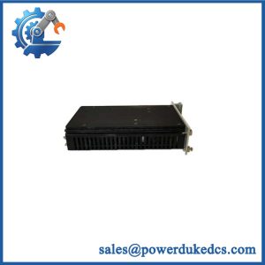
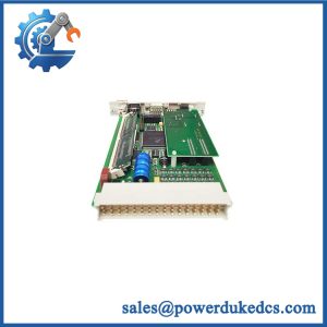
When an H51q installation approaches the available 5 VDC capacity of its existing central rack, replacing individual I/O modules will not solve the underlying supply problem. The HIMA B9361 997009361 is an additional-power assembly designed for H51q systems. Its purpose is to provide extra 5 VDC capacity while preserving redundant operation. The documented B9361 assembly is built around a K1408 central rack, 5 units high and 19 inches wide, with rear-side decoupling, fusing, fan monitoring, and supply monitoring hardware. The standard assembly includes one F7126 power-supply module, one F7131 monitoring module, and socket connectors for standard HIMA Planar modules.
The important rating is the additional 5 VDC load capability of up to 18 A. The B9361 can be expanded with two additional F7126 modules, giving three 24 V/5 V, 10 A power modules in the assembly; their 5 V outputs are configured for redundant operation. HIMA’s B9361 documentation states that the additional supply is intended when the installed central-rack power supplies are insufficient for the 5 V circuits, particularly when the required current exceeds 18 A in a redundant arrangement. The documentation also explicitly warns that the 5 V circuits of the central rack and additional supply must not be connected directly in parallel; their grounds are connected together instead.
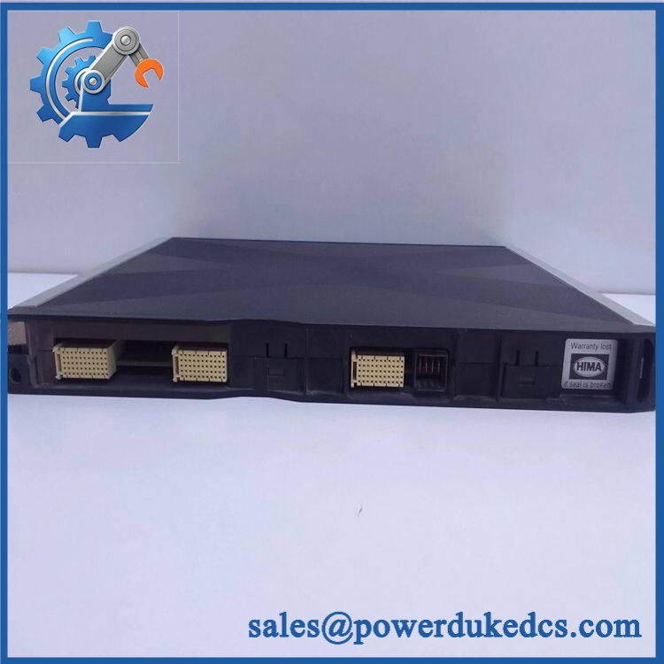
HIMA B9361 997009361
Module 4: Application Scenarios & Field Realities
- In an H51q control cabinet with a heavily populated I/O configuration, the B9361 becomes relevant when the combined 5 VDC consumption of the central and I/O modules exceeds the capacity available from the installed rack supplies. The correct engineering calculation is based on actual module current consumption, not simply the number of occupied slots.
- For redundant H51q control architectures, the three-F7126 arrangement provides the power redundancy required by the documented assembly concept. The design allows the 5 V supply to remain available when one of the three F7126 modules is unavailable, provided the total demand remains within the specified operating limits.
- When expanding a legacy cabinet with additional Planar 4 modules, provides a defined rack-level solution rather than adding an improvised external DC supply. The documented assembly provides 14 socket connectors for standard F-type HIMA modules, making the power assembly part of the intended Planar-system architecture.
- During a brownfield power investigation, inspect the as a complete assembly. Its rear-side architecture includes three Z6011 decoupling/fusing modules, a Z6012 fan with fan-run and fuse monitoring, and two Z6013 modules for supply-voltage decoupling and fusing. A fault in one of these auxiliary circuits can look like a general power-supply problem.
Module 5: Migration, Compatibility & Installation Traps
Replacement Matrix
Exact / 997009361 assembly: Drop-in Replacement
For an existing H51q installation using the same architecture, matching rack hardware, supply configuration, and connected modules, replacement of the complete assembly can normally be treated as a direct hardware exchange. The actual cabinet drawings remain the final installation reference.
with different F7126 population: Software Compatible / Hardware Verification Required
The standard assembly includes one , while two additional modules can be ordered separately. The number of installed units changes the power configuration, so the existing cabinet BOM and 5 VDC load calculation must be checked before assuming equivalence.
External 5 VDC power supply substituted for : Hardware Modification Required
Do not replace the with a generic high-current DC supply without an engineered redesign. The HIMA assembly incorporates redundancy, decoupling, fusing, fan monitoring, power monitoring, and defined grounding arrangements that an off-the-shelf supply does not automatically reproduce.
⚠️ Field Traps (Watch Out)
Do not parallel the 5 V circuits incorrectly: HIMA’s documentation explicitly states that the 5 V circuits of the power supplies in the central rack and the additional supply must not be switched in parallel. The GND connections are tied together, while availability is maintained through the redundant supply arrangement. An incorrect parallel connection can create a serious power-distribution fault.
18 A is a system-load boundary, not a marketing number: The additional power supply is documented as loadable up to 18 A. Before adding modules, calculate the actual +5 V consumption of the entire control configuration and account for redundancy. Do not use the 10 A rating of one as the total system capacity.
24 V input protection must be checked: The documentation specifies the 24 VDC supply connections and a maximum 16 A gL fuse for the PS1–PS3 supply feeds. Verify the cabinet protection scheme against the actual installed configuration before energizing a replacement assembly.
Module 6: Quality Assurance SOP
Pre-Shipment QA Protocol for HIMA 997009361
- Step 1 — Identity Verification: Confirm HIMA marking, designation, 997009361 order code where present, rack identification, installed /F7131 modules, and all visible auxiliary-module markings.
- Step 2 — OEM Anti-Counterfeit Visual Inspection: Examine HIMA labels, rack markings, module labels, terminal hardware, connector bodies, PCB markings where accessible, and assembly workmanship for inconsistencies or evidence of unauthorized modification.
- Step 3 — Mechanical Inspection: Inspect the 19-inch K1408 rack structure, 5U chassis, integrated cable tray, mounting points, card guides, rear connectors, socket connectors, and fan assembly for deformation, corrosion, contamination, or impact damage.
- Step 4 — Power-Module Verification: Confirm the installed modules are the correct HIMA variants and inspect each unit for label damage, connector wear, abnormal discoloration, or evidence of overheating.
- Step 5 — Power-On Self-Test: Energize the assembly from a controlled 24 VDC source and verify expected startup behavior of the and F7131 modules, including power-monitoring and diagnostic indications.
- Step 6 — 5 VDC Output Test: Measure the generated 5 VDC rail under controlled load. Verify voltage stability and document current capability without exceeding the test fixture’s approved limits.
- Step 7 — Redundancy Test: Where the laboratory setup permits, simulate loss of one supply and verify that the remaining configured supplies maintain the required 5 VDC output within the specified operating envelope.
- Step 8 — Fan and Monitoring Verification: Test the Z6012 fan operation, fan-run monitoring, fuse-monitoring circuit, and associated Z6013 supply path. Confirm that diagnostic states change as expected.
- Step 9 — Distribution and Connector Check: Verify socket-connector continuity, supply distribution, protective-fuse paths, and grounding arrangements before final release.
- Step 10 — Final QC Record: Record model, order code, installed submodule IDs, 24 V input measurement, 5 V output measurement, redundancy test result, fan-monitoring result, visual condition, test date, and final QC disposition.
Technical Verification Note: HIMA documentation identifies as an additional 5 V power-supply assembly for H51q systems. The documented package uses a K1408 19-inch, 5U rack, three Z6011 decoupling/fusing modules, one Z6012 monitored fan, two Z6013 decoupling/fusing modules, one 24 V/5 V 10 A supply as standard, one F7131 monitoring module, and optional additional units. The additional supply is specified for loads up to 18 A, with redundant 5 V operation and a defined non-parallel connection arrangement to the central-rack supply.



 Start Chat


