

Description
- Brand: HIMA
- Full Model Number: F7553
- System/Series Family: H51q / B9302 I/O Assembly
- One-Sentence Core Function: EABUS2 coupling module for monitoring the I/O subrack supply and managing the safety watchdog signal
- Top 3 Hardcore Specs: 5 VDC / 600 mA; 24 VDC / 750 mA; 4 TE space requirement
- Stock Status: Availability and exact revision to be confirmed against current inventory
Module 3: Technical Product Introduction
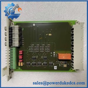
A failed coupling module in a HIMA H51q I/O rack is not a routine PLC card swap. The F7553 sits in the coupling path for the associated I/O subrack, monitors the 5 V supply, and transmits the corresponding status to the central module. Its front-panel WD indication shows the safety-related watchdog state, while the SEL indication identifies access to the associated I/O modules. A recessed WD switch provides a controlled method for switching off the watchdog signal before module replacement, preventing an unnecessary system error stop.
Power and rack utilization are straightforward on paper: the module requires 4 TE of space and is specified at 600 mA from 5 VDC and 750 mA from 24 VDC. Coding switches S1.1 through S1.4 are used to set the I/O bus cabinet and subrack assignment, so the replacement is not simply a matter of inserting a board with matching dimensions. HIMA’s published H41q/H51q revision list identifies F7553 as an EABUS2 connection module, revision 01, with the listed safety assessment valid under the cited report.
Module 4: Application Scenarios & Field Realities
- During an H51q I/O rack maintenance window, the F7553 is particularly relevant where the coupling module itself must be changed without immediately forcing the complete safety system into error stop. The WD switch has to be operated correctly before removal; the technical manual explicitly warns that failing to do so can place the entire system in error stop.
- For distributed H51q I/O cabinets, the four-position coding switch matters. S1.1–S1.4 establish the I/O bus assignment, allowing the coupling hardware to correspond to the intended cabinet and subrack rather than merely occupying the correct physical slot. Verify the original switch positions before removal and preserve them during replacement.
- Where power-supply diagnostics are part of the maintenance procedure, F7553 provides direct monitoring of the 5 V I/O subrack supply and passes the resulting status information to the central module. That makes it useful when troubleshooting rack-level supply or coupling faults rather than treating every communication alarm as a controller failure.
- For safety-system spare holding, revision control deserves attention. HIMA’s published revision list identifies F7553 as an EABUS2 connection module for the H41q/H51q family, with revision 01 listed as valid under the referenced certification report. Match the installed hardware revision and system documentation before releasing a warehouse spare to the field.
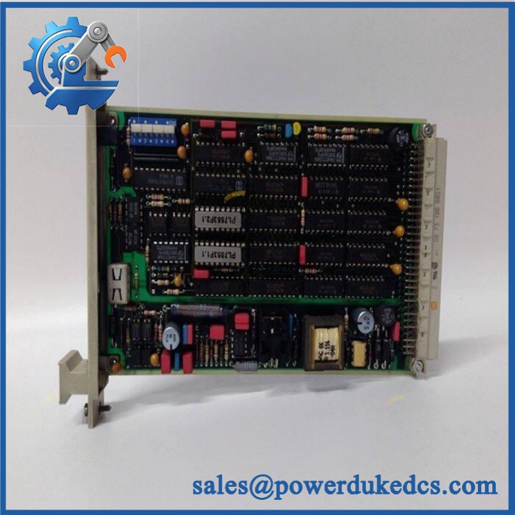
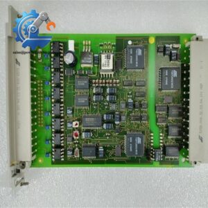
HIMA F7553
Module 5: Migration, Compatibility & Installation Traps
Replacement Matrix
Replacement Classification: Form-Fit Replacement Within the Specified H51q/B9302 Architecture
The is documented as a coupling module in assembly kit B9302 for the PES H51q system. It should therefore be treated as an architecture-specific replacement rather than a universal PLC interface. No general software recompile should be assumed solely because the is being replaced; the critical checks are the exact H51q configuration, hardware revision, I/O bus coding, and associated rack documentation.
⚠️ Field Traps — Watch Out
1. Watchdog switch sequence: Do not remove the module before placing the recessed WD switch in the required state. HIMA’s documentation states that replacing without operating the WD switch can cause the entire system to enter error stop. This is a maintenance-sequence issue, not a firmware issue.
2. Coding-switch mismatch: Record S1.1–S1.4 before extracting the existing unit. Those switches define the I/O bus cabinet and subrack assignment; copying the physical installation while leaving the coding wrong can produce an incorrect rack association. Also verify the 5 V and 24 V supply conditions against the installed rack documentation before energization.
Module 6: Quality Assurance SOP
Before shipment, the HIMA should pass a documented incoming and pre-shipment inspection sequence:
- OEM identification inspection: Check the HIMA nameplate, designation, markings, connector condition, PCB assembly, labels, and visible revision information against the available product documentation.
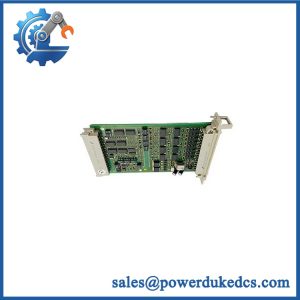
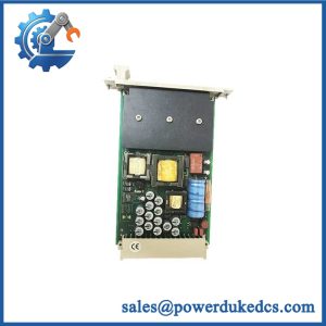
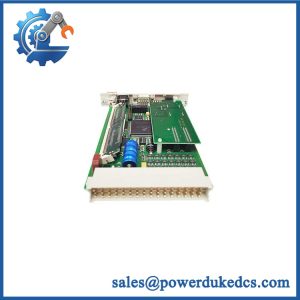
- Mechanical inspection: Examine the board, connector interfaces, mounting points, front-panel indicators, WD switch, and S1 coding-switch assembly for damage, contamination, oxidation, or evidence of prior mechanical stress.
- Configuration record: Photograph the S1.1–S1.4 switch positions on the supplied unit and record the hardware revision before dispatch. The switch settings are part of the I/O bus and subrack assignment.
- Power verification: Where the applicable HIMA test setup permits, verify operation against the documented 5 VDC / 600 mA and 24 VDC / 750 mA operating data.
- Power-on self-test (POST): Energize the module under the applicable rack test procedure and inspect the WD and SEL indicators for expected status behavior.
- Communication handshake verification: Confirm the coupling path and status exchange with the associated HIMA I/O rack and central module using the approved test configuration.
- Watchdog function check: Verify the WD indication and controlled watchdog switching behavior before release.
- Final QC record: Capture serial or identification markings, visual inspection results, electrical test results, configuration photographs, and final QC approval in the shipment record.
For this model, traceable configuration control matters as much as the physical condition of the spare. The is a safety-system coupling component with defined rack assignment and maintenance procedures, so the released unit should be matched to the customer’s exact H51q architecture before installation.



 Start Chat


