

Description
- Brand: HIMA
- Full Model Number: F3331
- System/Series Family: H41q / H51q / HIQuad
- One-Sentence Core Function: Eight-channel safety-related digital output module with integrated line monitoring and safety shutdown
- Top 3 Hardcore Specs: 8 output channels; 24 VDC field supply; 500 mA per channel, 12 W maximum load
- Stock Status: Stock condition and hardware revision to be confirmed
Module 3: Technical Product Introduction
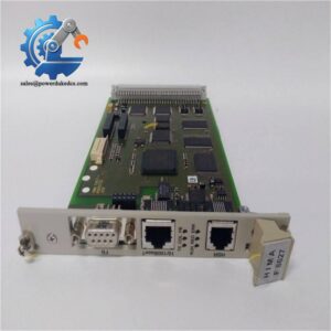
A failed digital output module can remove several field commands from service at once, particularly when valves, solenoids, contactors, or other final elements depend on the same I/O rack. HIMA F3331 is an eight-channel safety-related output module for H41q/H51q systems. Each channel can handle loads up to 500 mA, with short-circuit protection, integrated safety shutdown, output readback, and line-break monitoring. HIMA documentation classifies the F3331 as a safety-related assembly with SIL 3 capability.
The electrical limits are tightly defined. At a 500 mA load, the internal voltage drop is specified at a maximum of 2 V, while the total allowable line resistance is 11 Ω. Undervoltage shutdown occurs at approximately ≤16 V, short-circuit current is specified at 0.75–1.5 A, and output leakage current is limited to 350 µA. The module occupies 4 TE and requires approximately 130 mA at 5 VDC, with an additional 180 mA at 24 VDC for load circuits.
Module 4: Application Scenarios & Field Realities
- On emergency shutdown valves and solenoid-operated actuators, F3331 provides eight individually controlled digital outputs where the output state itself forms part of the safety function. The receiving load must stay within the 500 mA / 12 W channel limit; do not size the circuit from the nominal 24 V supply alone.
- For inductive loads, the internal protection and shutdown behavior are important during fault testing. HIMA specifies the module for resistive or inductive loads up to 500 mA, while lamp loads are limited to approximately 4 W. Check the actual actuator coil characteristics before commissioning.
- Where cable integrity has safety significance, the line-monitoring function provides a useful diagnostic layer. HIMA documentation specifies a line-break detection range of approximately 0.5–9.5 mA, while practical line-break monitoring requires a minimum load of 10 mA. A lightly loaded circuit may therefore need special review before relying on the diagnostic.
- In a crowded HIMA I/O rack, power and load count deserve attention. Published planning data permits up to 10 F3331 output modules with nominal load in one I/O rack. A replacement program should therefore check total field current and rack loading instead of treating every available slot as electrically equivalent.
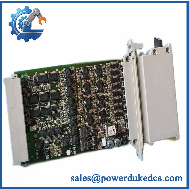
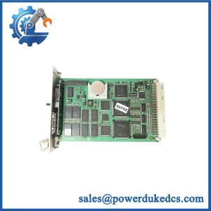
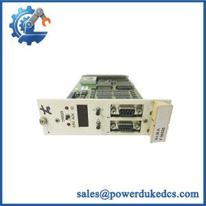
HIMA F3331
Module 5: Migration, Compatibility & Installation Traps
Replacement Matrix
Replacement Classification: Drop-in Replacement Within the Matching H41q/H51q Hardware Configuration
A like-for-like F3331 replacement is normally a direct hardware exchange when the existing system uses the same revision and compatible rack, field cable, and application configuration. HIMA’s revision list identifies as an 8-channel output assembly with line monitoring, with revisions 04 and 05 listed as valid under the referenced safety reports. Confirm the installed revision before releasing an older spare into a safety-related system.
No firmware flash or logic recompilation should normally be necessary for a same-model module replacement. The software-side point that matters is the approved application configuration and associated HIMA function block. Available documentation identifies HB-BLD- as the associated software building block for ; the exact software version should be matched to the installed HIMA operating-system release.
⚠️ Field Traps — Watch Out
1. Line-break monitoring requires sufficient loop load: HIMA planning information specifies a minimum 10 mA load for line-break monitoring. A replacement circuit that changes the connected load, adds a high-resistance interface, or uses an inappropriate field device may prevent the diagnostic from functioning as expected.
2. Output burden and cable resistance: At full 500 mA load, the module allows only 11 Ω total line resistance and can exhibit up to 2 V internal voltage drop. Long cable runs, terminal interfaces, or additional series devices can consume that voltage margin quickly. Calculate the complete loop rather than checking continuity alone.
Module 6: Quality Assurance SOP
The should undergo a documented electrical and configuration check before shipment.
- OEM identification visual inspection: Verify HIMA branding, designation, serial or identification label, hardware revision, PCB condition, terminal interface, and front-panel markings.
- Mechanical inspection: Examine the housing, PCB, connector pins, mounting guides, terminal interfaces, and evidence of corrosion, impact, contamination, or previous repair.
- Revision verification: Record the installed hardware revision and compare it with the customer’s existing documentation. HIMA’s published list identifies valid revisions including 04 and 05 under specified reports.
- Power verification: Apply the appropriate 5 VDC rack supply under an approved HIMA-compatible test setup and verify stable initialization.
- Power-on self-test (POST): Confirm normal startup behavior and inspect diagnostic/status indications before loading the channels.
- Eight-channel output test: Test each output independently at representative load conditions, including low, nominal, and near-rated current points where the test fixture permits.
- Short-circuit protection check: Verify protective behavior using a controlled test fixture, without exposing the production module to uncontrolled fault energy.
- Output readback verification: Confirm that commanded output states correspond to the measured electrical state. HIMA documentation identifies output readback as part of the automatic operating test.
- Line-break monitoring verification: Use a controlled simulated open-circuit condition and confirm the expected diagnostic response. Maintain the minimum loop-load requirement during the valid test configuration.
- Cross-talk and test-pulse verification: Check channel independence and verify the short diagnostic test-pulse behavior specified for the module.
- Final QC record: Retain hardware revision, identification photographs, eight-channel test results, load conditions, diagnostic observations, and final QC approval.
For , the important distinction is that this is not simply an eight-point digital output card. It combines safety-related output control with short-circuit protection, output readback, line monitoring, and an integrated safety shutdown function. HIMA’s current certification and revision documentation identifies as an eight-channel, safety-related output assembly with SIL 3 characteristics and a 500 mA / 12 W channel rating.



 Start Chat


