

Description
- Brand Motorola
- Full Model Number 01-W3839F-07A
- System/Series Family Motorola VMEbus processor / MVME2400-family cross-reference
- Core Function 6U VMEbus single-board computer for embedded processing and industrial control
- Top 3 Hardcore Specs 256 MByte memory configuration | PowerPC 750 350 MHz | VMEbus processor architecture
- Stock Status New Surplus — verify board marking, memory configuration, revision, and chassis compatibility before shipment
Module 3: Technical Product Introduction
A replacement processor board in a legacy VME chassis has to match more than the connector pattern. The supplied designation “4 256 MByte 01-W3839F-07A” is associated in secondary inventory references with a Motorola AP-4 256 MByte Processor Module, while other technical cross-references identify 01-W3839F-07A as the MVME2434-1, a 350 MHz PowerPC 750 VME processor with 256 MB ECC SDRAM. The cross-reference is supported by current component inventory records and specialist VME listings.
That identification should be handled carefully during procurement. The MVME2400 documentation and specialist listings describe a 6U VME architecture with PowerPC processing, ECC SDRAM, PMC expansion, VMEbus capability, Ethernet, serial I/O, and board-level diagnostics. Secondary pages also use the AP-4 designation for the same 01-W3839F-07A marking, but their published processor, I/O, and operating-system specifications are inconsistent. For an engineering replacement, the physical board identification, PCB revision, memory population, and installed firmware baseline should take precedence over an unverified AP-4 marketing description.
Module 4: Application Scenarios & Field Realities
- Inside a legacy VME industrial controller, the 01-W3839F-07A can serve as the central processing element while preserving the existing VME backplane and peripheral architecture. This is especially relevant when the application software and VME I/O cards are already qualified and a platform migration would introduce unnecessary engineering work.
- For data-intensive embedded control, the 256 MByte memory configuration provides considerably more working space than smaller MVME2400 variants. Specialist documentation for the cross-referenced MVME2434-1 identifies 350 MHz PowerPC 750 processing and 256 MB ECC SDRAM, which should be checked against the installed board before replacement.
- Where PMC hardware is installed, confirm the exact mezzanine-card population before dispatching a spare. The MVME2400 family was designed with PMC expansion, and the replacement board must preserve the installed I/O architecture rather than merely fitting the same VME slot.
- During an urgent VME chassis recovery, identification can be surprisingly difficult because the same assembly number appears under different commercial descriptions. One specialist listing explicitly matches 01-W3839F 07A to MVME2434-1, 350 MHz, 256 MB ECC SDRAM, while another secondary source labels the same number as an AP-4 256 MByte module. Photograph the PCB label and installed components before approving the replacement.
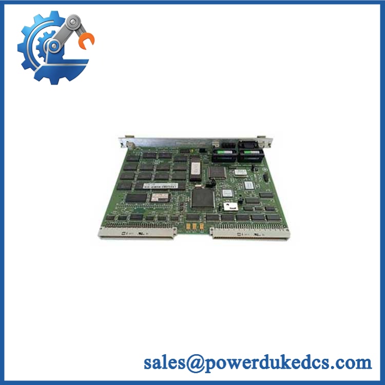
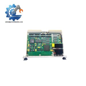
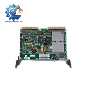
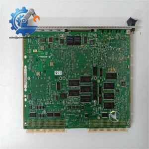
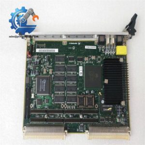
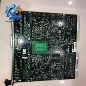
Motorola 01-W3839F-07A
Module 5: Migration, Compatibility & Installation Traps
Replacement Matrix
| Replacement Status | Engineering Assessment |
|---|---|
| Drop-in Replacement | Yes, when replacing the same 01–07A hardware in a compatible VME chassis with matching backplane, PMC configuration, firmware, and application environment. |
| Software Compatible | Generally yes for a like-for-like board replacement, but the existing BSP, boot parameters, operating-system image, NVRAM settings, and application software must be verified. |
| Hardware Modification Required | Normally no for an exact 01–07A replacement. Changes may be required when migrating to another VME processor family, changing PMC hardware, or altering the chassis architecture. |
⚠️ Field Traps: Watch Out
Do not normalize the part number solely from the phrase “AP-4 256 MByte.” Secondary references use that description f, while specialist VME references identify the same assembly number as MVME2434-1. The processor architecture and peripheral configuration should therefore be confirmed from the physical board before purchase.
Verify the memory implementation. The specialist MVME2434-1 reference identifies 256 MB ECC SDRAM, while other secondary pages give conflicting memory and processor figures for the same assembly number. Do not substitute a different MVME243x memory variant without checking the original system configuration.
Preserve NVRAM and boot configuration. A processor-board replacement can appear electrically healthy while failing to boot the customer’s application because of changed boot parameters, retained configuration, or firmware differences. Record the existing startup environment before removing the installed board.
Check PMC hardware before energization. Any PMC card, carrier arrangement, or custom daughterboard attached to the processor must be included in the compatibility check. A processor card can pass its own POST and still fail the production application because an expected mezzanine device is absent or incompatible.
Module 6: Quality Assurance SOP
A surpl should be tested as a complete VME processor assembly. Basic power-up is only the first acceptance gate.
- OEM anti-counterfeit visual inspection: Verify Motorola identification, marking, PCB revision, VME connector layout, faceplate, handles/ejectors, processor markings, memory devices, and visible board labels against controlled reference information.
- Part-number and traceability check: Record the complete assembly number, PCB revision, serial number, memory population, processor marking, and available date codes.
- Mechanical inspection: Examine P1/P2 VME connectors, PMC connectors, faceplate hardware, ejectors, heatsink, board edge, and PCB surface for bent contacts, corrosion, contamination, cracks, or unauthorized rework.
- Power-on self-test (POST): Install the board in a known-good compatible VME test chassis and verify normal processor initialization, diagnostic LEDs, board-fail behavior, and boot sequence.
- Memory verification: Test the complete 256 MByte memory population with an address and data-pattern test. Where the board is the MVME2434-1 configuration, verify ECC operation as part of the memory test.
- VMEbus verification: Confirm VMEbus master/slave access, representative address-space transactions, interrupt behavior, and system-controller operation where applicable.
- Ethernet verification: Test the available Ethernet interface under sustained transmit and receive traffic, monitoring packet errors and link stability.
- Serial-interface verification: Execute a controlled loopback test on the installed asynchronous serial interface and verify representative baud-rate settings.
- PMC verification: Where a PMC card is included with the customer’s approved configuration, confirm enumeration, bus access, and functional data exchange.
- Watchdog verification: Test the hardware watchdog through the approved service procedure and confirm the expected recovery behavior.
- RTC/NVRAM verification: Check real-time-clock retention and nonvolatile configuration storage while recording battery condition and retained settings.
- Boot and software verification: Boot the approved customer environment where authorized, confirm device recognition, and verify application startup without bus, memory, or I/O errors.
- Communication handshake verification: Verify actual VME and Ethernet data exchange through the intended test environment. A power LED or Ethernet link LED alone is not sufficient evidence of functional communication.
- Thermal and extended-run test: Operate the board under representative processor, memory, VME, Ethernet, and PMC loading while monitoring temperature, resets, bus errors, application stability, and intermittent faults.
- Final QC record: Document board identification, revision, memory size, processor type, POST result, VMEbus test, Ethernet test, serial test, PMC configuration, watchdog response, NVRAM/RTC condition, extended-run results, traceability data, and packing status.
Technical Identification Note: The supplied inventory description “MOTOROLA 4 256 MBy” appears to refer to the AP-4 256 MByte commercial description found in secondary listings. However, specialist VME documentation and current inventory references cross-reference to the , with a 350 MHz PowerPC 750 and 256 MB ECC SDRAM. Because the available secondary sources are inconsistent, the safest procurement record is to preserve the exact assembly number and verify the physical board before shipment.



 Start Chat


