

Description
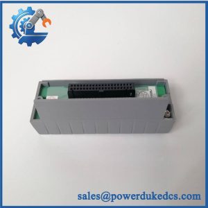
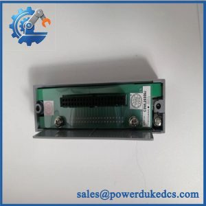
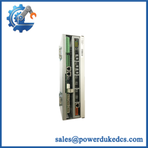
- Model: AAI135-H50/K4A00
- Brand: Yokogawa
- Series: AAI135 Analog Input Module
- Part Type: 8-channel isolated analog input module
- Core Function: Acquires eight isolated 4–20 mA DC signals while providing HART digital communication.
- Key Specs: 8 isolated channels; 4–20 mA input; HART communication; /K4A00 KS Cable Interface Adapter using ATK4A-00; 500 VAC withstand voltage.
- Lifecycle: Current replacement configuration for AAI135-H00/K4A00; specialist listings currently offer the H50 version, while H00 is identified as discontinued/replaced.
Product Introduction
A failed analog input channel in a running DCS can leave an instrumentation loop unavailable even when the field transmitter and cabinet wiring remain serviceable. Yokogawa AAI135-H50/K4A00 is an isolated 8-channel analog input module for 4–20 mA DC signals, with HART digital communication and a /K4A00 KS Cable Interface Adapter option using the ATK4A-00 interface. Yokogawa’s model coding confirms -H for HART communication, 5 for the non-explosion-protection version, and 0 for the basic type.
The module accepts input current up to 25 mA, provides 500 VAC withstand voltage between channels and between input and system, and has a 10 ms data update period. For legacy migration work, one important cross-reference stands out: AAI135-H50/K4A00 is documented by suppliers as the replacement for AAI135-H00/.
Core Technical Specifications
| Parameter | Value |
|---|---|
| Manufacturer | Yokogawa |
| Model | -H50/ |
| Series | |
| Product Type | Analog Input Module |
| Input Signal | 4–20 mA DC |
| Number of Channels | 8 |
| Channel Isolation | Isolated channels |
| Digital Communication | HART |
| Allowable Input Current | Up to 25 mA |
| Input Resistance, Power ON | 290 Ω at 20 mA; 450 Ω at 4 mA |
| Input Resistance, Power OFF | ≥500 kΩ |
| Transmitter Power Supply | ≥15.0 V at 20 mA; ≤29.3 V at 0 mA |
| Accuracy | ±16 µA |
| Data Update Period | 10 ms |
| Temperature Drift | ±16 µA per 10 °C |
| Withstand Voltage | 500 VAC for 1 minute |
| External Interface | KS Cable Interface Adapter |
| Interface Adapter | ATK4A-00 |
| Option Code | / |
| Operating Temperature | -20 to +70 °C |
| Humidity | 5–85% RH, non-condensing |
| Power Consumption | 360 mA at 5 VDC; 450 mA at 24 VDC |
| Reported Dimensions | 282 × 210 × 20 mm |
| Reported Weight | Approximately 0.3 kg |
The model and option coding is supported by Yokogawa-related specification material, while the detailed electrical values are corroborated by current technical listings.
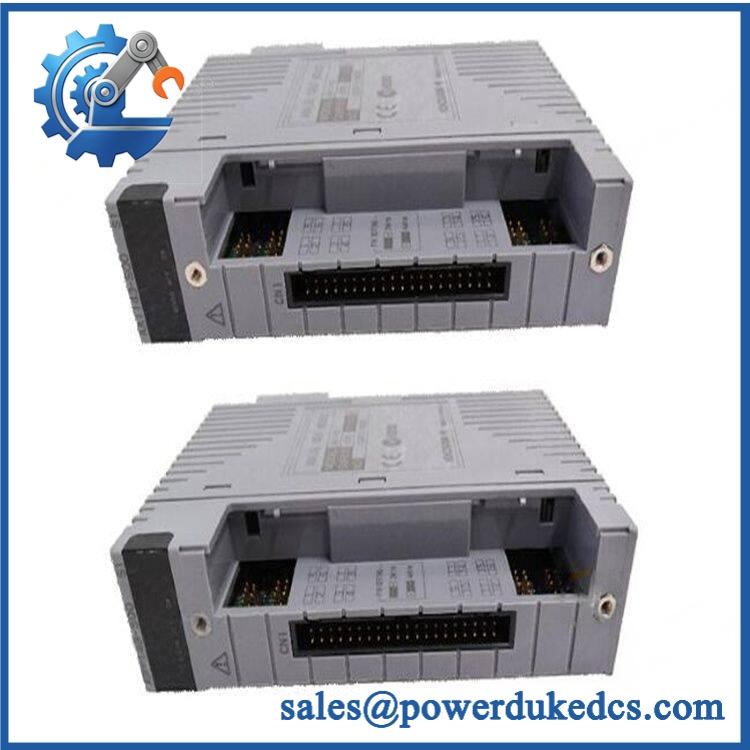
Yokogawa AAI135-H50/K4A00
Application Scenarios & Pain Points
In a chemical processing unit, eight isolated 4–20 mA loops can be handled by one -H50/, reducing the need to split instrumentation across multiple input modules. HART communication also permits digital transmitter information to accompany the analog process value.
For oil and gas instrumentation, the isolated-channel architecture is useful where ground-potential differences between field instruments could otherwise complicate signal acquisition. The module’s published 500 VAC isolation withstand specification is particularly relevant during engineering review.
During a refinery shutdown, replacing a failed -H00/ with the H50/ version can be considered as a lifecycle migration path because current supplier records identify the H50 configuration as its replacement. (Confirm the installed control-system revision before field installation.)
In power-generation plants, eight independent current inputs can serve transmitter loops for pressure, flow, level, or temperature transmitters, provided the signal characteristics match the configured input architecture.
Where cabinet temperatures approach 50°C or higher, environmental margin should be checked carefully. The published operating range extends to +70°C, while humidity is specified at 5–85% RH, non-condensing.
🚨 Common Error Codes & Diagnostic Symptoms
Symptom/Code: Multiple AI channels suddenly read zero or underrange
→ Diagnosis: Suspect loss of module power, KS interface connectivity, common wiring failure, or hardware failure rather than assuming all field transmitters failed simultaneously.
→ Action: Verify supply voltage, connector seating, loop current, and module diagnostics; replace the module if the hardware fails controlled channel testing.
Symptom/Code: One channel remains fixed despite a verified 4–20 mA source
→ Diagnosis: Possible failed input channel, damaged connector contact, or input circuitry fault.
→ Action: Substitute a calibrated current source at the affected channel and compare response with a known-good channel.
Symptom/Code: HART communication unavailable while the 4–20 mA value remains valid
→ Diagnosis: Analog acquisition may still function while the digital HART communication path or transmitter interface is impaired.
→ Action: Verify HART-enabled transmitter, loop wiring, module configuration, and communication status before replacing the module.
The itself does not use a conventional PLC-style numeric fault-code scheme in the published specifications, so troubleshooting is normally driven by channel behavior, diagnostics, input measurements, and system alarms.
🚨 Cross-Reference & Lifecycle Migration
Lifecycle Status: Replacement / Legacy migration item.
The most useful procurement cross-reference is -H00/ → -H50/. Specialist documentation explicitly identifies the H00/ unit as discontinued and the H50/ version as its upgrade/replacement.
Compatibility Assessment
- AAI135-H50/K4A00: Direct replacement, subject to configuration verification.
- / →00: Documented replacement path.
- / →00: Not equivalent. The
-Hcode adds HART communication, so the engineering function differs. - Firmware flashing: No routine firmware flash should be assumed solely because H50 replaces H00; verify the installed DCS hardware/software revision and module configuration first.
- Hardware modification: Normally unnecessary when the same interface arrangement is retained.
- Buffer-stock strategy: For a critical legacy CENTUM installation, hold a verified spare because H00 replacement demand shifts procurement toward the H50 configuration.
Current supplier listings continue to show as an active purchasable item, with quoted lead times ranging from approximately 1–10 business days to 8–10 weeks, depending on the supplier.
Field Engineer’s Tech Notes
First warning: do not ignore the / suffix. The family supports several external connection arrangements, including pressure-clamp and KS cable interfaces. / specifically identifies the ATK4A-00 KS Cable Interface Adapter. Ordering the base module without matching the external interface can create a cabinet-level wiring problem.
Second warning: verify the transmitter power budget. The published transmitter supply specification is at least 15.0 V at 20 mA and no more than 29.3 V at 0 mA. Do not assume every field transmitter will behave identically on the loop. Check the transmitter’s required burden voltage and the complete loop resistance before commissioning.
Strict QA & Testing SOP
- Inbound inspection: Verify Yokogawa markings, complete part number, serial/date information where available, packaging, and physical quantity.
- Nameplate verification: Confirm the
-H50configuration and/interface option before testing. - Physical examination: Inspect PCB surfaces, connectors, mounting hardware, adapter interface, terminals, labels, and signs of corrosion or unauthorized repair.
- ESD-controlled handling: Use an anti-static workstation, grounded wrist strap, and approved protective packaging throughout handling.
- Power verification: Apply the specified DC supply and record the module’s operating current under controlled conditions.
- POST check: Confirm normal startup, module recognition, status behavior, and absence of abnormal diagnostics.
- Current-source simulation: Feed calibrated 4, 8, 12, 16, and 20 mA signals to representative channels and verify corresponding values.
- Full-channel test: Exercise all eight input channels rather than testing only one representative point.
- Isolation test: Verify channel-to-channel and channel-to-system isolation using the approved laboratory method and safety limits.
- HART test: Connect a known-good HART transmitter or approved simulator and verify digital communication where the test environment supports it.
- Input-limit test: Confirm controlled operation below, within, and near the upper input range without exceeding the manufacturer’s permitted limits.
- Transmitter supply test: Measure loop supply behavior under representative load conditions.
- Temperature-stability test: Run representative load conditions while monitoring module temperature and signal stability.
- Power-cycle test: Perform controlled shutdown/startup cycles and verify repeatable module initialization.
- Final QC release: Record measured currents, HART results, supply readings, channel status, hardware revision, photographs, and inspector approval.
- Packaging: Seal the tested module in ESD-safe packaging with connector protection and shock-resistant outer packaging.
- Test evidence: Test videos are available for applicable inspection and live-rig verification.
The documented technical values support a 10 ms data update period, ±16 µA accuracy, 500 VAC withstand testing, and 8-channel isolated acquisition.
Buyer’s FAQ
Q1. Can I hotthe / while the DCS is running?
A: Do not treat this as a general-purpose live-service operation. Follow the Yokogawa system’s approved maintenance procedure and site MOC requirements. A live module exchange can interrupt multiple analog loops or create transient process values.
Q2. How can I verify that a Newnal / is the correct unit?
A: Check the complete designation. The -H50 identifies the HART, non-explosion-protection, basic configuration, while / specifies the ATK4A-00 KS Cable Interface Adapter.
Q3. My existing module is -H00/. Can I order H50/?
A: Current specialist documentation identifies /K4A00 as the replace 5-H00/K4A00. Engineering should still verify the CENTUM configuration and installed hardware revision before the change.
Q4. Does the replacement require firmware flashing?
A: There is no basis to assume a firmware flash is required solely from the H00-to-H50 change. The controlling checks are system compatibility, module configuration, HART requirements, and the installed DCS revision. Verify these parameters before commissioning.
Q5. What warranty should procurement require?
A: Require written coverage for DOA and functional failure, the warranty period, return authorization procedure, inspection window, and return freight terms. Current supplier listings advertise 12-month warranty coverage on some new units, but the warranty in the purchase quotation should control.



 Start Chat


