

Description
-
- Model: AAI835-H50/K4A00
- Brand: Yokogawa
- Series: AAI835 Analog I/O Series
- Part Type: Isolated Analog I/O Module
- Core Function: Handles four isolated 4–20 mA inputs and four isolated 4–20 mA outputs within a Yokogawa DCS I/O architecture.
- Key Specs: HART-enabled; 4 input + 4 output channels; 4–20 mA signal range; 500 VAC channel/system isolation;
/K4A00option with ATK4A-00 KS Cable Interface Adapter. - Procurement Signal: Current supplier listings show stock claims, but lead-time reports vary from 1–10 business days to 4–5 months, so physical stock confirmation is essential.
Product Introduction
Structure B — Technical direct:
Within the Yokogawa analog I/O architecture, AAI835 is the combined current-I/O module providing four 4–20 mA inputs and four 4–20 mA outputs with isolated channels. The-Hcode specifies HART digital communication,5indicates the non-explosion-protection version, and/K4A00specifies the ATK4A-00 KS Cable Interface Adapter.For plants maintaining long-lived CS3000 or related Yokogawa installations, this combination is useful when both analog sensing and analog control are required in the same module position. The published electrical data includes 500 VAC withstand isolation between I/O and the system and between I/O channels, while the 4–20 mA inputs have a specified maximum input current of 25 mA.
Core Technical Specifications
Parameter Value Manufacturer Yokogawa Model AAI835 Complete Configuration AAI835-H50/K4A00 Product Type Analog I/O Module Input Channels 4 Output Channels 4 Input Signal 4–20 mA Output Signal 4–20 mA Channel Isolation Isolated channels HART Supported ( -Hsuffix)Explosion Protection Not provided ( 5suffix)Temperature Option Basic type ( 0suffix)Cable Interface ATK4A-00 via /K4A00Allowable Input Current 25 mA Input Accuracy ±16 µA Output Accuracy ±48 µA Withstand Voltage 500 VAC for 1 minute Approx. Module Weight 0.2 kg Yokogawa’s published specification identifies the AAI835 as a 4-channel input / 4-channel output isolated current I/O module. The manufacturer also defines
/K4A00as the ATK4A-00 KS Cable Interface Adapter option.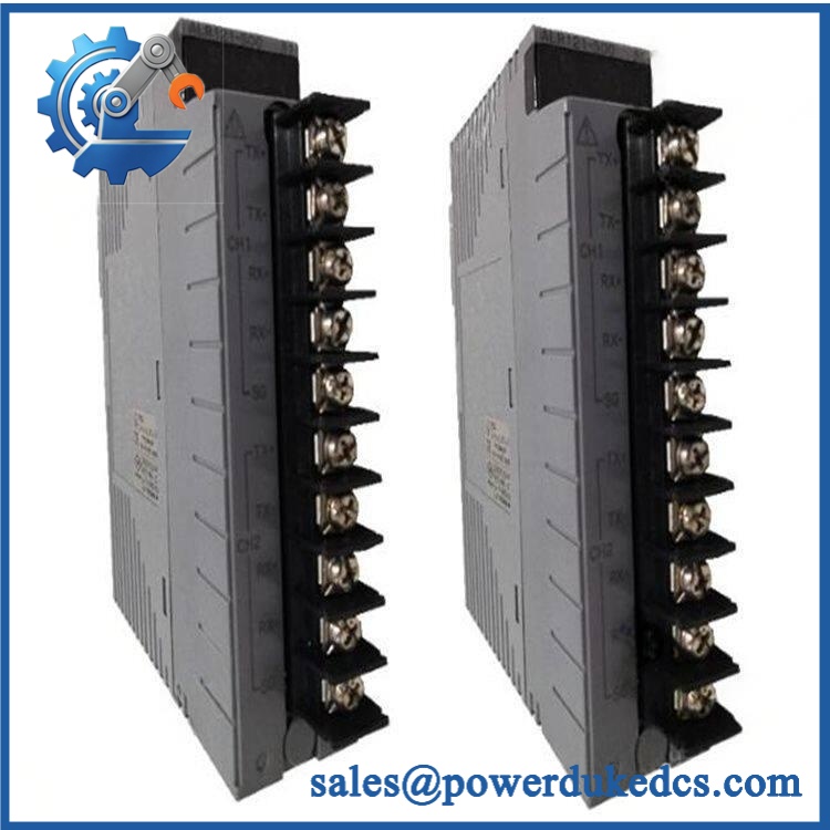
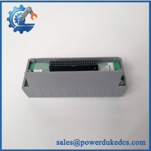
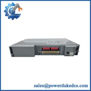
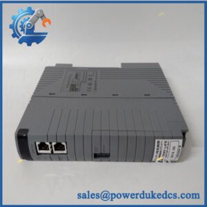
Yokogawa AAI835-H50/K4A00
Application Scenarios & Pain Points
A refinery loop-recovery case: a failed mixed analog I/O module can take both measurement and control functions out of service. Replacing the preserves the four-channel input/four-channel output architecture without splitting the application across two different module types.
In chemical processing, HART-enabled 4–20 mA channels are useful where instrument diagnostics and process variables need to travel through the same analog loop. The -H configuration specifically adds HART communication capability.
For power-generation auxiliary systems, isolated analog channels help reduce the impact of field-side electrical differences. The published withstand rating reaches 500 VAC for one minute between the I/O and system and between isolated channels.
During legacy migration, the
/option becomes a key procurement detail. It identifies the ATK4A-00 KS Cable Interface Adapter, so an apparently correct without the required interface configuration may still require cabinet-side changes.At the cabinet level, a failed module may present as multiple unrelated loop faults. When four inputs and four outputs become unavailable together, check the common I/O module, cable interface, and backplane path before replacing individual field instruments.
🚨 Common Error Codes & Diagnostic Symptoms
Symptom/Code: Multiple 4–20 mA channels simultaneously read zero or abnormal values
→ Diagnosis: A common module, KS interface, connector, or backplane problem is more likely than simultaneous transmitter failure.
→ Action: Verify module seating, cable interface, loop continuity, and module diagnostics; replace the if the hardware test fails.Symptom/Code: Analog output channels remain fixed or fail to respond to command changes
→ Diagnosis: Internal output-channel circuitry, connector contacts, or the I/O module interface may be defective.
→ Action: Test each output with a calibrated load and compare commanded versus measured current; replace the module when channel response remains outside specification.Symptom/Code: HART communication unavailable while 4–20 mA remains present
→ Diagnosis: The analog loop may still be functional while the HART communication path or module configuration has failed.
→ Action: Verify that the installed unit is the-Hconfiguration, then test HART communication before replacing the module.🚨 Cross-Reference & Lifecycle Migration
Lifecycle Status: Current availability appears configuration-dependent; not confirmed as discontinued by Yokogawa. Yokogawa maintains a formal discontinued-products database, but the current results reviewed do not identify as discontinued. At the same time, independent suppliers report materially different lead times, indicating that procurement availability should be treated separately from technical lifecycle status.
Known configuration distinction: Yokogawa defines:
— 4-channel input / 4-channel output isolated analog I/O-H— HART communication5— no explosion protection0— basic type/— ATK4A-00 KS Cable Interface Adapter
Previous revision / replacement relationship: One current supplier record explicitly identifies -H50/ as a replacement for -H00/. Treat that as a supplier-reported cross-reference rather than a blanket engineering equivalence until the installed system documentation is checked.
Firmware flashing: No blanket firmware-flash requirement is established for this hardware from the published specifications reviewed. Compatibility should instead be checked through module type, HART requirement, cable-interface option, I/O configuration, and host-system revision.
Buffer-stock strategy: For a production-critical cabinet, one or two tested spare modules are reasonable where downtime cost is high—especially when the required
/configuration has a reported procurement lead time extending to several months.Field Engineer’s Tech Notes — Anti-Pitfall Guide
First warning: do not buy by
alone. The complete suffix matters.-Hchanges the communication capability,5identifies the no-explosion-protection version, and/specifies the cable interface. Match the complete ordering code to the cabinet drawing before issuing the PO.Second warning: do not assume a healthy 4–20 mA reading proves the entire module is good. The combines inputs and outputs. A unit can pass a basic analog-loop check while an output channel or HART function remains faulty. Test representative input, output, and communication functions separately (especially after long-term storage).
Strict QA & Testing SOP
Step 1 — Inbound Verification
Record-H50/, serial number, hardware revision, manufacturer markings, and packaging condition.Step 2 — OEM Visual Inspection
Inspect the PCB, connectors, module housing, terminal/interface arrangement, labels, and identification markings for inconsistencies or signs of unauthorized repair.Step 3 — Mechanical Check
Verify card-edge condition, mounting points, connector alignment, and enclosure integrity. Check for corrosion, bent contacts, cracked plastic, or heat damage.Step 4 — Electrical Pre-Test
Perform controlled continuity and insulation checks appropriate to the module and test setup. Do not apply an unsuitable megohmmeter or hipot test directly across sensitive electronic circuitry.Step 5 — Power-Up / POST
Install the module in a compatible Yokogawa test environment. Verify normal initialization, module recognition, and absence of diagnostic abnormalities.Step 6 — Analog Input Test
Inject calibrated 4–20 mA signals into all four input channels. Record measured values and verify performance against the specified input accuracy of ±16 µA.Step 7 — Analog Output Test
Command representative 4–20 mA output values on all four output channels using an approved test configuration. Measure the delivered current and verify performance against the specified output accuracy of ±48 µA.Step 8 — HART Test
For the-Hconfiguration, connect an approved HART test instrument and verify digital communication, device recognition, and stable communication while the analog loop remains active.Step 9 — Isolation Verification
Where the laboratory procedure permits, verify the documented isolation characteristics using an appropriate certified test method. Yokogawa specifies 500 VAC for one minute for the relevant withstand tests.Step 10 — KS Interface Verification
Confirm the/interface connection and verify pin mapping against the approved Yokogawa wiring documentation.Step 11 — Extended Run Test
Operate all input/output channels under representative conditions. Monitor signal stability, HART communication, module temperature, intermittent faults, and restart behavior.Step 12 — Final QC Record
Record identification, input measurements, output measurements, HART results, isolation-test results where performed, interface verification, and final acceptance status.Packaging: Use ESD-protective packaging, connector protection, moisture control, and impact-resistant outer packaging. Test videos are available for procurement and engineering review.
Buyer’s FAQ — Dynamic Q&A
Q1. Can I hot-swap the -H50/?
Do not assume it is safe to remove or insert the module under power. A live I/O change can create false process signals, unexpected analog outputs, HART communication interruptions, or control-system alarms. Follow the approved Yokogawa maintenance procedure for the specific system.Q2. I found an with a different suffix. Is it the same thing?
Not necessarily. The suffix defines important functional characteristics. In particular,-Hindicates HART communication, while/specifies the KS Cable Interface Adapter. Match the complete configuration, not just the base model.Q3. Is -H50/ genuinely available as a new original unit?
Current supplier listings advertise new stock, but reported lead times vary sharply—from 1–10 business days at one source to 4–5 months at another. That difference is enough to justify physical inventory confirmation and written condition/origin confirmation before PO release.Q4. Does this module need firmware flashing when replacing an older ?
No universal firmware requirement is established from the manufacturer specifications reviewed. The key engineering checks are the exact suffix, HART requirement, cable-interface option, I/O configuration, and host-system compatibility.Q5. What warranty should procurement require?
Specify a written functional warranty covering all four analog inputs, all four analog outputs, HART communication for the-Hconfiguration, and the/interface under defined acceptance conditions. The PO should also include the RMA process and exclusions for incorrect installation, field wiring faults, electrical overstress, and unauthorized modification.



 Start Chat


