

Description
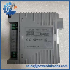
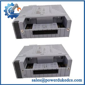
- Model: AAI143-S00 S1
- Brand: Yokogawa
- Series: AAI143 Analog Input Module Series
- Part Type: Isolated Analog Input Module
- Core Function: Acquires sixteen isolated 4–20 mA process signals for compatible Yokogawa FIO/DCS architectures.
- Key Specs: 16 isolated inputs; 4–20 mA signal; 24 mA allowable input; 10 ms data update period; ±16 µA accuracy; 1500 VAC isolation rating.
- Configuration: S1 style; exact suffix should be matched against the installed module and system documentation.
Product Introduction
Structure B — Technical Direct
Installed at the Yokogawa FIO I/O level, the AAI143 provides 16 isolated 4–20 mA analog input channels for process transmitters. Yokogawa specifies a 10 ms data-update period, ±16 µA accuracy, 24 mA allowable input current, and 1500 VAC withstand voltage between the input and system. Each channel can be configured for 2-wire or 4-wire transmitter operation through the module’s setting pin.
For long-running DCS installations, that combination matters during legacy migration and spare-parts planning. The module is compatible with pressure-clamp terminal, dedicated-cable, and MIL-connector connection arrangements, depending on the associated interface hardware. Yokogawa’s connection documentation specifically lists AAI143 as a 16-channel isolated 4–20 mA analog input module.
Core Technical Specifications
| Parameter | Value |
|---|---|
| Manufacturer | Yokogawa Electric Corporation |
| Model | AAI143 |
| Complete Configuration | AAI143-S00 S1 |
| Product Type | Isolated Analog Input Module |
| Input Channels | 16 |
| Input Signal | 4–20 mA DC |
| Channel Isolation | Isolated from system; channels are not individually insulated from one another |
| Allowable Input Current | 24 mA |
| Input Resistance, Power ON | 270 Ω at 20 mA to 350 Ω at 4 mA |
| Input Resistance, Power OFF | 500 kΩ or greater |
| Accuracy | ±16 µA |
| Data Update Period | 10 ms |
| Transmitter Supply | 19.0 V or higher at 20 mA; 25.5 V or lower at 0 mA |
| Transmitter Supply Current Limit | 25 mA |
| Withstand Voltage | 1500 VAC for 1 minute between input and system |
| Transmitter Type | 2-wire or 4-wire, selectable per channel |
| Typical Application | Yokogawa FIO / DCS analog input |
| Connection Options | Pressure-clamp terminal, dedicated cable, or MIL connector depending on interface configuration |
These values are taken primarily from Yokogawa’s published specifications. The exact S1 style designation should still be confirmed against the physical nameplate before procurement.
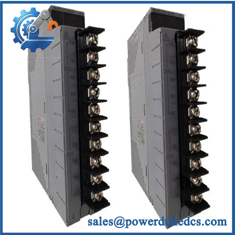
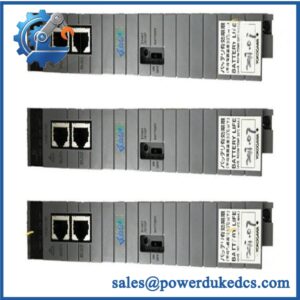
Yokogawa AAI143-S00 S1
Application Scenarios & Pain Points
A refinery transmitter loop failure: when several process values suddenly disappear from one cabinet, the common module becomes a logical inspection point. Sixteen channels share one module position, so a single hardware failure can affect multiple measurements simultaneously.
In chemical processing, the module suits conventional 4–20 mA transmitter networks where accurate multi-channel acquisition is required. Its specified update period is just 10 ms, useful for control applications where input refresh frequency matters.
For power-generation auxiliaries, isolated input architecture helps separate field-side signals from the system interface. Yokogawa specifies 1500 VAC for one minute between the input side and system side.
During a cabinet retrofit, the transmitter wiring must match the configured input arrangement. permits 2-wire or 4-wire transmitter selection per channel, so replacing the module without recording those settings can produce incorrect loop behavior.
At high ambient temperatures, cabinet cooling deserves attention. Around 50°C and above, engineers should inspect ventilation, terminal condition, and module temperature rather than assuming a recurring analog fault is purely software-related.
🚨 Common Error Codes & Diagnostic Symptoms
Symptom/Code: Multiple AI channels simultaneously read low or zero
→ Diagnosis: A common module, connector, terminal-board, or cable-interface fault can affect several channels at once; simultaneous transmitter failure is less likely.
→ Action: Verify module seating, field supply, cable continuity, and calibrated loop input; replace the if the module fails bench testing.
Symptom/Code: One 4–20 mA channel remains fixed despite a verified transmitter
→ Diagnosis: The individual input circuit, terminal connection, or channel configuration may be defective.
→ Action: Inject a calibrated current directly at the approved test point; replace the module when the measured response remains outside specification.
Symptom/Code: Transmitter works in 4-wire mode but fails after replacement
→ Diagnosis: The affected channel may have been configured for the wrong 2-wire/4-wire setting. supports per-channel selection.
→ Action: Verify the channel setting pin and wiring against the approved Yokogawa configuration.
🚨 Cross-Reference & Lifecycle Migration
Lifecycle Status: Current technical documentation supported; exact commercial availability is inventory-dependent. Yokogawa continues to publish specifications and connection information, but published technical documentation alone does not guarantee immediate physical stock.
Compatibility family: is specifically the 16-channel isolated 4–20 mA analog input module. It should not be confused with AAI141, which Yokogawa identifies as a 16-channel non-isolated 4–20 mA input module.
Connection cross-reference: can be used with pressure-clamp terminal, dedicated cable, or MIL-connector connection arrangements depending on the selected cabinet interface. The terminal hardware therefore needs to be identified before ordering.
Firmware flashing: No module-specific firmware-flashing requirement is established by the published hardware specification. The key checks are I/O configuration, transmitter wiring, interface hardware, and host-system compatibility.
Buffer-stock strategy: For a production-critical FIO cabinet, maintain at least one tested spare matching the complete installed configuration. Where dozens of loops depend on one module, the economic exposure from a single failure can exceed the value of keeping a spare on-site.
Field Engineer’s Tech Notes — Anti-Pitfall Guide
First warning: record every channel’s transmitter wiring before pulling the module. supports both 2-wire and 4-wire transmitters, selected individually. A replacement with incorrect channel settings can create what looks like a failed transmitter even when the instrument is healthy.
Second warning: do not change the connection method casually. Yokogawa supports several signal-connection arrangements, but the associated terminal board, dedicated cable, or MIL interface is part of the installation design. Confirm the exact interface before substituting a different cable or adapter (especially during cabinet refurbishment).
Strict QA & Testing SOP
Step 1 — Inbound Identification
Record -S00 S1, serial number, hardware revision, manufacturer markings, and all visible identification labels.
Step 2 — OEM Visual Inspection
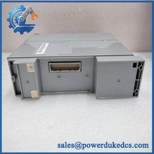
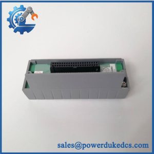
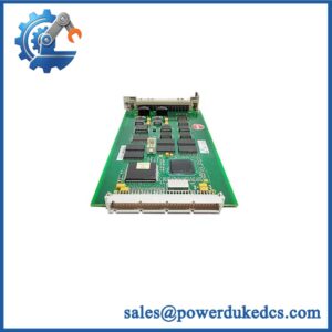
Inspect the housing, connector, card-edge contacts, status indicators, labels, PCB markings, and mounting hardware. Look for corrosion, contamination, impact damage, or unauthorized repair.
Step 3 — Mechanical Check
Verify connector alignment, module guides, card-edge condition, retention points, and enclosure integrity.
Step 4 — Electrical Pre-Test
Check relevant continuity and isolation conditions using a test method suitable for the electronics. Do not apply an inappropriate insulation or hipot voltage directly across sensitive circuits.
Step 5 — Controlled Power-Up
Install the module in a compatible Yokogawa test rack. Confirm normal startup, module recognition, and absence of abnormal diagnostics.
Step 6 — Analog Input Calibration Test
Inject calibrated 4–20 mA signals into all 16 channels. Record measured values at representative points such as 4, 12, and 20 mA. Compare results with the specified ±16 µA accuracy.
Step 7 — Channel Configuration Test
Where the test fixture supports it, verify 2-wire and 4-wire transmitter configurations on representative channels. Confirm that the transmitter supply remains within the documented range.
Step 8 — Input Resistance Check
Verify representative power-on input resistance against the documented 270–350 Ω range across the current span, using a controlled measurement method.
Step 9 — Update-Rate Verification
Run a controlled signal transition and verify the expected data-refresh behavior. The published update period is 10 ms.
Step 10 — Isolation Verification
Where the laboratory procedure and test equipment permit, verify the specified input-to-system withstand characteristic using an approved safety-rated method. The documented rating is 1500 VAC for one minute.
Step 11 — Extended Run Test
Operate representative channels under continuous current input while monitoring signal stability, module temperature, supply behavior, and intermittent channel faults.
Step 12 — Final QC Record
Document module identification, all channel measurements, configuration checks, isolation-test results where performed, extended-run observations, and final QC disposition.
Packaging: Use ESD-protective packaging, connector protection, moisture control, and impact-resistant outer packaging. Test videos are available for procurement and engineering review.
Buyer’s FAQ — Dynamic Q&A
Q1. Can I hot-swap the -S00 S1?
Do not assume live removal is acceptable. is connected to active analog loops, and disconnecting those circuits can create process alarms, false readings, or unexpected control responses. Follow the approved Yokogawa maintenance procedure for the installed FIO architecture.
Q2. How do I verify a New Original -S00 S1?
Check the complete model/style marking, serial number, manufacturer identification, connector configuration, PCB construction, and hardware revision. Then require a functional test showing verified 4–20 mA performance rather than relying on packaging or cosmetic condition.
Q3. Is -S00 S1 the same as AAI141?
No. Yokogawa identifies as isolated and AAI141 as non-isolated 16-channel 4–20 mA analog input hardware. They should not be treated as interchangeable without engineering approval.
Q4. Does require firmware flashing during replacement?
No general firmware-flashing requirement is established for the module itself. Engineering should focus on transmitter type, per-channel configuration, terminal/cable interface, and host-system compatibility.
Q5. What warranty should procurement require?
Specify a written functional warranty covering power-up, all applicable 4–20 mA input channels, transmitter-supply behavior, configuration verification, and stable operation under defined test conditions. The PO should include the RMA process and exclusions for incorrect wiring, field faults, electrical overstress, and unauthorized modification.



 Start Chat


