

Description
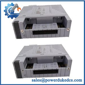
- Model: PW482-50 S2
- Brand: Yokogawa
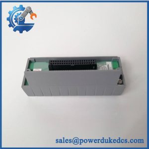
- Series: PW482 Power Supply Module
- Part Type: AC-input DCS power supply module
- Core Function: Supplies dedicated operating power to Yokogawa Field Control Units, FIO Node Units, and Optical ESB Bus Repeater Units.
- Key Specs: 220–240 V AC input; ±10% input tolerance; 50/60 Hz ±3 Hz; maximum power consumption 230 VA; exclusive system connector; approximately 1 kg.
- Lifecycle: Active documented S2 hardware generation; Yokogawa’s 2021 specification identifies PW482 as a current power-supply module family and supports dual-redundant installation.
Product Introduction
The power supply is often the first component to become critical when an FCU cabinet develops a fault. Yokogawa PW482-50 S2 is the 220–240 V AC input member of the PW482 family, intended for installation in Yokogawa Field Control Units, FIO Node Units, and Optical ESB Bus Repeater Units. Two identical power-supply modules can be installed for a dual-redundant configuration, reducing the consequence of a single module failure.
The -50 configuration corresponds to 220–240 V AC with no explosion protection, while the basic -0 configuration is reflected in Yokogawa’s model-ordering conventions. One important engineering point: Yokogawa explicitly states that the PW48x output voltage and current are not specified as generic power-supply ratings, because these modules are dedicated to Yokogawa system units rather than general-purpose DC power applications.
Core Technical Specifications
| Parameter | Value |
|---|---|
| Manufacturer | Yokogawa Electric Corporation |
| Model | PW482-50 S2 |
| Series | PW482 |
| Product Type | Power Supply Module |
| Primary Application | FCU, FIO Node Unit, Optical ESB Bus Repeater Unit |
| Input Voltage | 220–240 V AC |
| Input Tolerance | ±10% |
| Input Frequency | 50/60 Hz ±3 Hz |
| Maximum Power Consumption | 230 VA |
| Connection | Exclusive Yokogawa system connector |
| Redundancy | 2 modules for dual-redundant configuration |
| Weight | Approximately 1 kg |
| Output Rating | Not specified as a standalone generic DC output |
Explosion Protection, -50 |
No explosion protection |
| Hardware Generation | S2 |
| External Dimensions | Approximately 190 × 149 × 49.7 mm* |
*Dimensions are taken from Yokogawa’s published PW48x module drawing; verify the exact mechanical drawing for the installed cabinet configuration.
Yokogawa’s specification is clear that is a dedicated system power module, so published figures such as a generic “24 V DC output” or a standalone wattage rating should not be used for engineering substitution without the applicable Yokogawa system documentation.

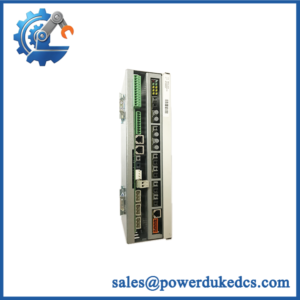
Yokogawa PW482-50 S2
Application Scenarios & Pain Points
A Yokogawa FCU operating in a petrochemical control room may continue running normally until one reaches an end-of-life condition. With dual-redundant power installed, the second module can maintain the system while maintenance replaces the failed unit. Yokogawa explicitly supports two PW48x modules for this redundancy arrangement.
For FIO Node Units, provides the dedicated AC power conversion required by the Yokogawa architecture rather than acting as a freely interchangeable industrial DC supply. This distinction matters when an MRO team evaluates generic substitutes.
In optical ESB repeater installations, the same family is specified as a compatible power-supply module. Yokogawa documentation lists PW481, , and PW484 according to the required input-power type.
During planned shutdown maintenance, replacing a before deterioration develops can reduce exposure to capacitor and power-component aging. Yokogawa’s installation guidance gives the a recommended 8-year replacement cycle for the relevant applications when average ambient temperature is 40 °C or less.
At higher cabinet temperatures, that published replacement-cycle assumption should not be applied without engineering review; thermal stress is a major factor in power-supply aging.
🚨 Common Error Codes & Diagnostic Symptoms
Symptom/Code: FCU power alarm / not recognized
→ Diagnosis: Possible loss of AC input, internal power-conversion failure, connector fault, or module hardware failure.
→ Action: Verify the incoming 220–240 VAC supply and system connector, then replace the if the module fails controlled testing.
Symptom/Code: Repeated power-supply switchover or redundant-module alarm
→ Diagnosis: One member of the dual-redundant power pair may be unstable or unable to carry its intended system load.
→ Action: Check each independently using the approved Yokogawa maintenance procedure and replace the failing unit.
Symptom/Code: FCU or FIO node intermittent reset
→ Diagnosis: Unstable power conversion, connector contact degradation, or an upstream AC supply problem can cause repeated system disturbances.
→ Action: Record input voltage and system diagnostics, inspect both modules, and replace the suspect module after confirming the external supply is normal.
The family does not use a universal standalone numeric fault-code scheme in the published general specification. Diagnosis is normally based on system alarms, module status, power behavior, and cabinet-level diagnostics.
🚨 Cross-Reference & Lifecycle Migration
Lifecycle Status: Active documented S2 generation; periodic replacement item.
Yokogawa’s official PW48x specification identifies PW481, , and PW484 as the three input-voltage variants:
- PW481: 100–120 V AC
- 220–240 V AC
- PW484: 24 V DC
The -50 ordering configuration corresponds to the no-explosion-protection version for the relevant voltage family. Yokogawa’s ordering documentation lists PW482-50 as 220–240 V AC / no explosion protection.
Compatibility Assessment
- -50 S2 → -50 S2: Direct like-for-like replacement, subject to cabinet and system verification.
- PW4 → : Not compatible as a simple substitution because the input-voltage family differs.
- PW4 → : Not compatible as a simple substitution because PW484 is the 24 V DC input family.
- Firmware flashing: Not normally applicable to the power module itself.
- Hardware modification: Normally unnecessary for an idal S2 replacement.
- Buffer-stock strategy: Yokogawa recommends an 8-year replacement cycle for in specified applications at average ambient temperatures of 40 °C or less. For critical FCU/FIO assets, planned spare coverage is therefore justified rather than waiting for field failure.
Field Engineer’s Tech Notes
First warning: match the input family exactly. Do not confuse PW481, , and PW484 because they share the same mechanical family. is the 220–240 V AC version; PW481 is 100–120 V AC, while is 24 V DC.
Second warning: do not use generic DC-output figures from third-party listings. Yokogawa explicitly says the output voltage and current of PW48x modules are not specified as generic power-supply ratings because these are dedicated system modules. (That matters when a replacement proposal is being built from a catalog rather than the Yokogawa system drawing.)
Strict QA & Testing SOP
- Inbound inspection: Verify Yokogawa markings, complete identification, quantity, packaging, and visible condition.
- Nameplate verification: Confirm ,
-50configuration, S2 hardware generation, and applicable voltage designation. - Physical examination: Inspect the housing, exclusive connector, mounting surfaces, ventilation openings, terminals, and signs of corrosion or overheating.
- Revision recording: Capture serial number, date code, hardware revision, and any visible manufacturing identifiers.
- ESD-controlled handling: Keep the module protected during inspection and test.
- Electrical baseline check: Inspect for shorts, damaged components, contaminated contacts, and mechanical connector defects before energization.
- Controlled AC power-up: Apply an approved 220–240 VAC test supply within Yokogawa’s specified tolerance and monitor startup behavior.
- Input-current measurement: Record operating input current under controlled test conditions.
- Status verification: Confirm expected power/module status indications and absence of abnormal system alarms in the compatible test setup.
- Load/system test: Install the in an approved Yokogawa FCU/FIO test arrangement and confirm stable system operation under representative load.
- Redundancy test: Where a dual-module test setup is available, verify proper operation when one is removed from service according to the approved procedure.
- Power-cycle test: Perform controlled startup and shutdown cycles and confirm repeatable initialization.
- Thermal observation: Monitor temperature rise during representative operation, paying particular attention to cabinet environments approaching elevated ambient conditions.
- Connector integrity check: Confirm secure engagement and inspect for intermittent contact under controlled mechanical observation.
- Final QC release: Record input measurements, system-test results, revision data, photographs, inspector approval, and packaging condition.
- Packaging: Use ESD-safe protection with connector shielding and shock-resistant outer packaging.
- Test evidence: Test videos are available for applicable bench and system-integration inspections.
Yokogawa’s published guidance treats as a replaceable power-supply module and specifies an 8-year recommended replacement cycle for defined applications under average ambient conditions of 40 °C or less.
Buyer’s FAQ
Q1. Can I hot-she S2 while the FCU is running?
A: Do not assume live replacement is permissible merely because the system uses dual redundancy. Follow the Yokogawa installation and maintenance procedure for the specific FCU/FIO application. The redundant architecture is intended to maintain system availability, but the removal procedure still has to match the installed hardware configuration.
Q2. How do I confirm a New Oal S2 is the correct unit?
A: Verify the complete designation and confirm that the installed system requires 220–240 V AC input. Also check the enclosure, exclusive connector, hardware revision, and system application. and belong to different input-voltage families.
Is S2 a generic 24 V DC power supply?
A: No. Yokogawa specifically states that the PW48x series is an exclusive module for FCUs, FIO Node Units, and Optical ESB Bus Repeater Units and does not specify output voltage/current as generic supply ratings.
Qes S2 require firmware flashing after replacement?
A: Not normally. This is a dedicated power module rather than a processor or I/O module. The key checks are correct voltage variant, mechanical interface, system compatibility, and stable operation after installation.
Q5. What warranty should procurement require?
A: Require written coverage for DOA and functional failure, a defined warranty period, return authorization procedure, inspection window, and return-freight terms. For a critical DCS power module, the quotation should also state the exact revision, physical condition, test status, and actual-stock availability.



 Start Chat


