

Description
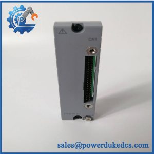
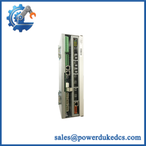
- Model: AAI143-S50
- Brand: Yokogawa
- Series: AAI143 Analog I/O Module for FIO
- Part Type: 16-channel isolated analog input module
- Core Function: Converts field 4–20 mA transmitter signals into digital data for the Yokogawa control system.
- Key Specs: 16 isolated channels; 4–20 mA DC input; 10 ms data update period; ±16 µA accuracy
- Transmitter Support: 2-wire / 4-wire selection by channel setting pin
- Redundancy: Dual-redundant configuration supported
- Input Protection: 24 mA allowable input current
- Condition: New Original / New Surplus / Tested Refurbished — verify physical stock before PO
Yokogawa’s official specification identifies AAI143 as a 16-channel isolated 4–20 mA analog input module and confirms dual-redundant operation.
Product Introduction
Inside a Yokogawa FIO installation, the AAI143-S50 sits between field transmitters and the control-system data path. Sixteen isolated channels accept standardized 4–20 mA DC signals, while the module converts those measurements into internal FCS data. A 10 ms data-update period supports process measurements that require faster refresh than many conventional analog-input interfaces. The standard S50 configuration is the basic, non-explosion-protected version of AAI143.
In field deployments, this module is commonly relevant when an installed CENTUM VP/FIO node needs a like-for-like spare rather than a redesigned I/O architecture. Each channel can be configured for 2-wire or 4-wire transmitter use by the module’s setting pin, so the replacement must match the existing field wiring. Yokogawa documentation also identifies AAI143 within current FIO installation and technical documentation, while the manufacturer’s public discontinued-product database does not currently list -S50 as a discontinued item.
Core Technical Specifications
| Parameter | Value |
|---|---|
| Model | -S50 |
| Product Type | Analog Input Module |
| Input Channels | 16, isolated |
| Input Signal | 4–20 mA DC |
| Allowable Input Current | 24 mA |
| Accuracy | ±16 µA |
| Data Update Period | 10 ms |
| Input Resistance | 270 Ω at 20 mA to 350 Ω at 4 mA |
| Transmitter Supply | 19.0 V or higher at 20 mA; 25.5 V or less at 0 mA |
| Transmitter Supply Current Limit | 25 mA |
| Transmitter Type | 2-wire or 4-wire, selected per channel |
| Withstanding Voltage | 1500 V AC, 1 minute, input-to-system |
| Redundancy | Dual-redundant configuration supported |
| Suffix | S = Standard type; 5 = no explosion protection; 0 = basic type |
| Weight | Approximately 0.3 kg |
The electrical figures above come from Yokogawa’s published specifications. The S50 suffix structure is documented as standard type + no explosion protection + basic type.
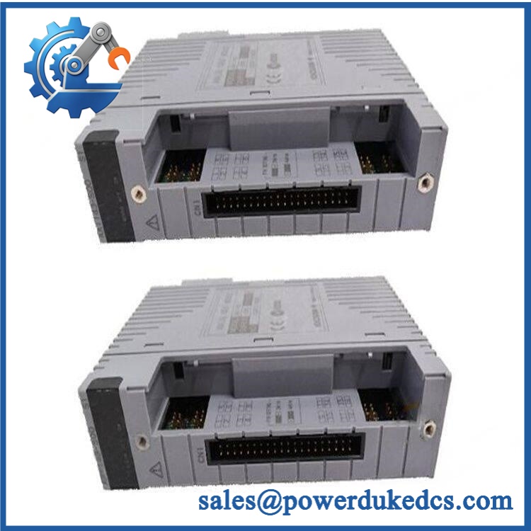
Yokogawa AAI143-S50
Application Scenarios & Pain Points
A shutdown caused by one failed analog channel can become a cabinet-level procurement problem when the installed I/O architecture is legacy. With 16 isolated 4–20 mA inputs on one module, -S50 is suited to dense transmitter applications where replacement wiring would consume more outage time than the module exchange itself.
- Oil and gas: Pressure, flow, level, and temperature transmitters can feed the sixteen current-input channels. In installations reaching 50°C+ ambient temperatures, verify the applicable environmental rating for the exact hardware configuration before returning the node to service.
- Refining: Multiple process transmitters can be grouped within one FIO node, reducing the need for separate input cards. The isolated channel architecture helps separate field loops from the system side.
- Chemical processing: For corrosive or electrically noisy process areas, isolation and controlled transmitter-supply characteristics become important during loop troubleshooting.
- Power generation: Where a CENTUM VP node remains in service, a tested spare avoids unnecessary cabinet reconfiguration and retermination during a planned outage.
- Water and utilities: Four-to-twenty milliamp instruments remain common on pumps, treatment skids, and distributed measurement points; the 10 ms update period supports frequent process-data refresh.
🚨 Common Error Codes & Diagnostic Symptoms
Symptom/Code: One or more channels remain at 0 mA / underrange
→ Diagnosis: Open field loop, incorrect transmitter wiring, blown external protection, or loss of the module’s transmitter supply. Check the loop before condemning the -S50.
→ Action: Verify loop continuity and channel wiring; replace the module only after the field circuit is proven healthy.
Symptom/Code: Multiple channels show simultaneous abnormal readings
→ Diagnosis: A module-level power, bus, or internal signal-processing fault becomes more likely when several unrelated field loops fail together.
→ Action: Check node diagnostics and module status, then replace the -S50 with a verified spare if the module is identified as faulty.
Symptom/Code: Input value is stable but consistently offset from the calibrated transmitter signal
→ Diagnosis: Incorrect wiring mode, channel configuration, input-loop resistance, or analog front-end degradation can produce a persistent measurement error.
→ Action: Confirm the 2-wire/4-wire setting and measured loop current; replace the module if the error follows the card.
Yokogawa specifies channel-level 2-wire/4-wire selection and a defined input resistance, so wiring configuration should be checked before declaring hardware failure.
🚨 Cross-Reference & Lifecycle Migration
- Lifecycle Status: Current documentation / not identified as discontinued in Yokogawa’s public discontinued-product listings reviewed for this check. Yokogawa continues to publish -related FIO installation and technical documentation.
- Base Model: — 16-channel isolated 4–20 mA analog input module.
- S50 Meaning: S = Standard type; 5 = no explosion protection; 0 = basic type.
- Known Variant: -H50 is the HART-enabled variant; it should not be treated as identical to the S50 version when HART functionality is required.
- Other Configuration Path: Yokogawa also documents variants with explosion protection and ISA G3/temperature options. Confirm the complete suffix before substitution.
- Firmware Requirement: No module-specific firmware flash should be assumed for a standard like-for-like S50 replacement. System release compatibility and node configuration should still be checked before commissioning.
- Buffer Stock Strategy: For a critical CENTUM VP/FIO node, maintain at least one tested spare where failure would cause a process shutdown or significant maintenance delay.
A particularly important cross-check: is not the same procurement itAAI143-H50. The latter adds HART functionality, so substituting between them can change the installed instrument-management capability.
Field Engineer’s Tech Notes
First warning: Do not change the transmitter wiring mode by assumption. supports both 2-wire and 4-wire transmitter arrangements by channel setting pin. Before pulling the old card, photograph the relevant settings and terminal connections. One misplaced setting can turn a healthy transmitter into an apparent input-card failure.
Second warning: Watch the loop behavior when the module is powered off. Yokogawa documentation states that the current-input loop becomes open when power is off or abnormal, and it cautions against connecting the current signal directly to another receiving device without the appropriate external receiver arrangement. Check the complete loop before energizing a replacement.
During handling, use ESD controls. The connector and PCB should never be treated like ordinary cabinet hardware.
Strict QA & Testing SOP
Step 1 — Inbound Inspection
- Match the physical label to Yok.
- Record serial number, hardware revision, date information, and visible manufacturing codes.
- Perform OEM marking and anti-counterfeit visual inspection.
- Photograph the front, rear, connectors, and nameplate.
Step 2 — Mechanical Inspection
- Check connector pins for bending or contamination.
- Inspect the PCB and enclosure for corrosion, impact, overheating, or unauthorized repair.
- Verify card-edge and mounting features.
Step 3 — Electrical Checks
- Verify insulation condition using an approved test procedure.
- Check input-to-system isolation.
- Confirm the test fixture provides the correct module power conditions.
- Verify channel resistance behavior against the specified input characteristics.
Step 4 — Live Rig Testing
- Install the module in a compatible Yokogawa FIO test environment.
- Perform power-up diagnostics.
- Confirm module recognition and status.
- Exercise all sixteen channels with calibrated current sources.
Step 5 — Analog Accuracy Test
- Test representative channels at approximately 4 mA, 12 mA, and 20 mA.
- Compare measured values against calibrated references.
- Confirm performance against the specified ±16 µA accuracy.
Step 6 — Transmitter Interface Test
- Test both representative 2-wire and 4-wire configurations.
- Verify transmitter-supply output under controlled load.
- Confirm the current-limit behavior remains within the documented specification.
Step 7 — Isolation Test
- Verify channel/system isolation using an approved laboratory procedure.
- Do not connect a Zener barrier where Yokogawa documentation prohibits it; use the specified isolation arrangement for intrinsically safe applications.
Step 8 — Communication and System Test
- Confirm reliable data transfer to the FCS.
- Verify channel values remain stable during extended operation.
- Where dual-redundant service is required, test the approved redundant configuration.
Step 9 — Final QC
- Record all measured values against the serial number.
- Issue a signed QC/Test Report.
- Apply a QC Passed label.
- Package the module in anti-static protection with connector protection.
Test evidence: Test videos and the serial-number-specific QC report should be available for procurement review before shipment.
Buyer’s FAQ
Q1. Can I hot-swa?
Do not assume that it is safe to remove the module under power simply because the FIO architecture supports redundant configurations. Confirm the installed node type, redundancy arrangement, site maintenance procedure, and process impact first. Yokogawa documents dual-redundant use for , but that does not mean every installation can be serviced live.
Q2. How do I know a “New Orig is actually the correct unit?
Match the physical nameplate to , then verify the suffix configuration: standard type, no explosion protection, basic type. Ask for serial-number photographs and inspection evidence before shipment.
Q3. My engineers need HART. Is S50 the right version?
Not necessarily. Yokogawa separately identifies the -H suffix for HART communica is the standard version; do not approve an S50 replacement when the application specifically depends on HART functionality.
Q4. What should be in the warranty and return terms?
The quotation should state the exact part number, physical condition, serial number, warranty period, functional coverage, return authorization process, and test scope. For a surplus unit, require a pre-shipment QC report tied to the supplied serial number.
Q5. What is the safest spare-stock policy for this module?
For a critical FIO node, keep a tested spare on hand rather than waiting for a failure. The module contains sixteen process inputs, so one failed card can affect a large group of transmitters at once. (That exposure is especially important where a maintenance window is measured in hours, not days.)



 Start Chat


