

Description
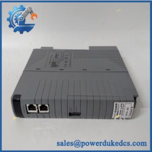
- Model: AAR181-S50 S2
- Brand: Yokogawa
- Series: CENTUM VP / CENTUM CS FIO
- Part Type: Isolated RTD Input Module
- Core Function: Collects resistance-temperature signals from field RTD sensors and transfers 12 isolated temperature measurements into the Yokogawa FIO system.
- Key Specs: 12 isolated channels, 3-wire Pt100 input, ±5 V allowable input range, 1500 V AC field-to-system withstand rating, approximately 1 mA excitation per channel, and pressure-clamp terminal connectivity.
Product Introduction
Inside a Yokogawa CENTUM FIO node, the AAR181 occupies the temperature-input position for resistance temperature detector measurements. The module provides 12 isolated RTD channels, with the documented AAR181 specification supporting 3-wire Pt100 sensors and isolation between the field circuit and system side. For process plants maintaining older CENTUM installations, this makes the AAR181-S50 S2 a relevant legacy migration and spare-parts item rather than a generic analog input card.
The complete ordering code matters here. Yokogawa’s documentation identifies AAR181 as a 12-channel isolated RTD input module and lists the standard, non-explosion-protected -S5-0 configuration. The specific S2 hardware revision should therefore be matched to the installed unit’s nameplate and engineering records before substitution.
Core Technical Specifications
| Parameter | Value |
|---|---|
| Manufacturer | Yokogawa Electric Corporation |
| Model | AAR181-S50 S2 |
| Product Type | 12-Channel Isolated RTD Input Module |
| System Family | CENTUM VP / CENTUM CS FIO |
| Input Channels | 12 |
| Input Type | RTD |
| Standard Sensor | Pt100, 3-wire |
| RTD Standard | JIS C1604 / IEC 751 references in Yokogawa documentation |
| Allowable Input Voltage | ±5 V DC |
| Field-to-System Withstand | 1500 V AC for 1 minute |
| Input Resistance | 2 MΩ or greater, powered or unpowered |
| Measurement Excitation | Approximately 1 mA per channel |
| Burnout Detection | Supported on applicable configurations |
| External Connection | Pressure-clamp terminal configuration |
| Installation | Yokogawa FIO node/rack |
| Typical Application | Process temperature measurement |
| Operating Environment | Check the exact suffix and system-generation specification before installation |
Yokogawa’s published specification confirms the 12-channel isolated RTD architecture, Pt100 input, ±5 V allowable input voltage, and 1500 V AC withstand rating. A current secondary source reports approximately 1 mA channel excitation and burnout diagnostics for the S2-marked unit.
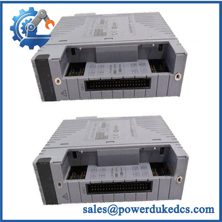
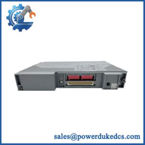
YOKOGAWA AAR181-S50 S2
Application Scenarios & Pain Points
A temperature loop can become a plant reliability issue long before the process alarm becomes obvious. When several RTD points suddenly drift, drop out, or show burnout indications, engineers need to determine whether the problem sits in the sensor, field wiring, terminal assembly, or FIO module.
Petrochemical Reactors and Heat Exchangers
The is designed for multi-point RTD acquisition, making it suitable for reactor skin temperature, bearing temperature, heat-exchanger monitoring, and similar process measurements. Its 12 isolated channels allow several measurements to share one FIO module while maintaining electrical separation.
Refinery and Chemical Process Units
For 3-wire Pt100 instrumentation, a failed input channel can appear as an incorrect process temperature rather than a complete communications failure. Proper resistance checks at the sensor terminals can distinguish field problems from module-side faults.
Power Generation Equipment
Temperature monitoring of auxiliaries, lubrication systems, bearings, and other equipment can require multiple RTD channels concentrated in a single control node. A known-good spare becomes valuable when an installed FIO node is supporting several critical temperature loops.
Brownfield CENTUM CS/VP Systems
Yokogawa’s hardware documentation guide shows that was removed from the documented product lineup in May 2021, which is a strong lifecycle signal for sites still operating this hardware.
High-Temperature Cabinets
At 50°C+ ambient conditions, inspect terminal tightness, sensor wiring, cabinet ventilation, and module temperature carefully. RTD errors are often blamed on electronics when the actual cause is field wiring resistance or thermal degradation.
Common Error Codes & Diagnostic Symptoms
Because the is an I/O module rather than a standalone controller, exact numeric alarms depend on the connected CENTUM system and software revision. Physical symptoms are more useful for first-line diagnosis.
Symptom/Code: RTD Burnout / Open-Circuit Alarm
→ Diagnosis: An open Pt100 circuit, broken sensor lead, loose terminal, or failed input channel can trigger burnout detection.
→ Action: Measure the RTD resistance at the field side first; repair the wiring or replace the when the fault follows the module.
Symptom/Code: Temperature Reading Stuck or Grossly Incorrect
→ Diagnosis: Incorrect 3-wire termination, unequal lead resistance, damaged input circuitry, or an improperly matched sensor can produce a fixed or badly shifted reading.
→ Action: Verify the sensor wiring and resistance values, then substitute a tested module if the abnormal reading remains channel-specific.
Symptom/Code: Multiple RTD Channels Lost Together
→ Diagnosis: When several otherwise independent temperature channels fail simultaneously, suspect the module interface, backplane connection, or common communication path before replacing individual sensors.
→ Action: Check FIO node diagnostics and module seating; replace the -S50 S2 if the failure follows the hardware.
Cross-Reference & Lifecycle Migration
Base model identification:
Yokogawa’s official documentation defines as an RTD Input Module, 12-channel, isolated. The standard suffix structure shown in the original general specification includes -S5-0, meaning standard type, without explosion protection, basic type.
Related connection hardware:
Unlike 16-channel FIO modules such as AAI141 or AAV141, Yokogawa’s connection table shows using ATR8S/ATR8D terminal hardware rather than the ATK4A/KS1 arrangement. That distinction is important when ordering a replacement assembly.
Revision caution:
The supplied part is marked S2, but available public Yokogawa documentation does not establish a universal “S2 replaces all prior revisions” rule. Match the full nameplate and terminal arrangement to the existing installation instead of treating S2 as an automatic drop-in across every implementation.
Firmware:
The itself is an I/O module and does not normally require a user firmware flash like a PLC CPU. System software and FIO configuration compatibility still need to be checked before commissioning a replacement.
Lifecycle status:
Obsolete / Legacy. Yokogawa’s current hardware-document guide records the deletion of from its listed hardware documentation in May 2021.
For an operating plant, that status supports keeping tested buffer stock on hand. Do not base the maintenance plan solely on spot-market availability.
Field Engineer’s Tech Notes
First warning: do not use a 2-wire RTD termination where the application expects 3-wire Pt100. Lead resistance affects the measured value, and an incorrect termination can look like calibration drift or a bad module. Check the loop against the Yokogawa wiring diagram before replacing the electronics.
Second warning: check the terminal assembly before condemning the . Yokogawa specifies dedicated ATR8S/ATR8D terminal arrangements for . A mismatched or poorly seated terminal connection can affect an entire group of RTD channels (particularly after panel maintenance).
Strict QA & Testing SOP
1. Inbound inspection
Verify the complete YOKOGAWA AAR181-S50 S2 marking, hardware revision, terminal interface, enclosure condition, connector condition, and nameplate information.
2. Traceability check
Photograph the identification label and record serial or manufacturing information where available. Compare the physical part against the purchase specification.
3. Mechanical inspection
Inspect the terminal interface, module guides, contact areas, housing, and retaining hardware for bent contacts, contamination, corrosion, or impact damage.
4. Controlled power-up
Install the module in a compatible Yokogawa FIO test environment. Confirm module recognition, status indication, communications, and diagnostic behavior.
5. RTD channel simulation
Connect calibrated resistance sources representing appropriate Pt100 temperatures to representative channels. Confirm that resistance changes are correctly interpreted by the module.
6. Multi-channel verification
Exercise the 12 input channels rather than checking only one point. Record the displayed or transmitted temperature values and compare them with the reference resistance.
7. Burnout test
Where supported by the test setup, open the RTD circuit intentionally and verify the expected burnout/open-circuit diagnostic response.
8. Isolation verification
Verify the specified field-to-system isolation test requirements using an approved test procedure and appropriate safety equipment. Yokogawa documents a 1500 V AC, 1-minute withstand specification.
9. Extended operation
Run the module through a sustained test while monitoring temperature stability, diagnostics, communications, and channel repeatability.
10. Calibration record
Document reference resistance, measured value, channel number, test instrument identification, and acceptance result.
11. Final QC and packaging
Record photographs, serial information, test results, technician approval, and condition classification. Package the module in ESD-safe protection with mechanical support around the terminal interface.
12. Evidence package
Supply the QC/test report with the unit. Test videos are available to document power-up, channel testing, and burnout-diagnostic verification.
Buyer’s FAQ
Q: Is -S50 S2 the same type of module as AAV141?
A: No. is specifically a 12-channel isolated RTD input module for Pt100 measurement, while AAV141 is a voltage-input module. Their electrical functions and field wiring are different.
Q: Can I replace the module without shutting down CENTUM?
A: The belongs to the Yokogawa FIO architecture, but whether online replacement is permitted depends on the exact CENTUM configuration, node arrangement, and approved maintenance procedure. Do not remove a live module solely because the hardware appears plug-compatible.
Q: How do I verify a “New al” S2?
A: Request clear photographs of the full model marking and revision, terminal interface, serial information, and factory packaging. For obsolete hardware, ask for an actual functional-test report rather than relying on a condition label.
Q: Does obsolete status mean I should stock several units?
A: It depends on plant criticality and installed quantity. Since Yokogawa’s documentation guide removed from its listed hardware in May 2021, sites that remain dependent on the module should maintain a documented spare strategy, with at least one tested replacement for critical channel groups.



 Start Chat


