

Description
- Model: CP451-10 S2
- Brand: Yokogawa
- Series: CENTUM VP / CS3000 FCS Processor Module
- Part Type: Processor Module
- Core Function: Executes the FCS application program and manages real-time control processing and communications within a Yokogawa field control station.
- Key Specs: Style S2; dual Vnet/IP bus architecture; 40 MIPS processor; 128 KB RAM; 1 MB Flash; 24 VDC system environment. Independent technical listings identify CP451-10 S2 as a Yokogawa processor module, while Yokogawa documentation confirms dual-redundant processor configurations use identical processor modules with matching model codes.
- Procurement Status: Legacy / Discontinued according to current independent lifecycle references; retain tested spare stock where this processor remains plant-critical.
Product Introduction
Structure B — Technical Direct
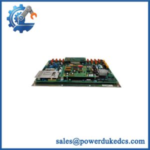
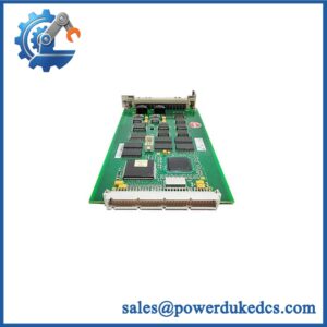
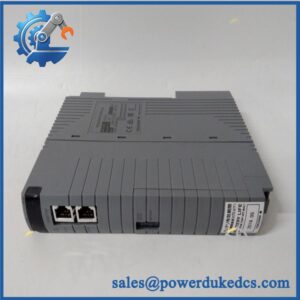
The CP451-10 S2 is a Yokogawa processor module used within the field control station architecture. Current technical references identify the unit as a Style S2 processor with dual Vnet/IP bus capability, a 40 MIPS processor, 128 KB RAM, and 1 MB Flash memory. The module is programmable, so its actual behavior depends on the application program loaded into the processor.
For a legacy CENTUM VP or CS3000 installation, the processor is not an ordinary plug-in spare. Application version, processor revision, redundancy arrangement, and communication configuration all matter. Yokogawa documentation describes dual-redundant FCS operation using two identical processor modules with the same model code, allowing control authority to transfer when one side becomes defective.
Core Technical Specifications
| Parameter | Value |
|---|---|
| Manufacturer | Yokogawa |
| Model | CP451-10 S2 |
| Product Type | Processor Module |
| Style | S2 |
| Processor Speed | 40 MIPS* |
| RAM | 128 KB* |
| Flash Memory | 1 MB* |
| Communication | Dual Vnet/IP bus architecture* |
| System Supply | 24 VDC environment* |
| Application | Yokogawa FCS / DCS |
| Programming | Application-program dependent |
| Redundancy | Dual-redundant FCS supported |
| Redundant Pair | Two identical processor modules with the same model code |
| Approx. Weight | 0.74 kg* |
| Lifecycle | Legacy / Discontinued according to independent lifecycle listings |
*These detailed hardware figures are reported by current independent technical listings rather than the Yokogawa documents retrieved for this response; verify the physical nameplate and applicable Yokogawa specification before treating them as procurement acceptance values.
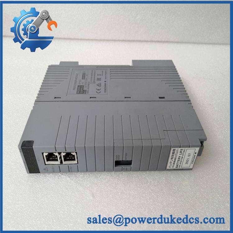
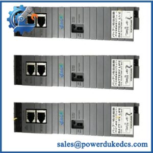
Yokogawa CP451-10 S2
Application Scenarios & Pain Points
A refinery FCS recovery case: when the active processor develops a hardware fault, the immediate requirement is control continuity—not a full DCS replacement. In a properly configured redundant FCS, Yokogawa specifies that a second identical processor can assume control without interrupting the control function.
For power-generation auxiliary control, CP451-10 S2 processors can remain in service long after the surrounding platform has become difficult to source. At ambient conditions approaching 55°C, cabinet ventilation and processor temperature should be checked before returning a replacement to service.
During chemical-plant maintenance, a processor replacement can preserve the existing control application and field I/O architecture, provided the replacement hardware and loaded application are compatible. The key engineering task is configuration verification.
On a legacy CS3000 migration project, keeping one tested CP451-10 S2 as a contingency spare can protect the plant during staged migration. A failed processor can otherwise turn a planned migration schedule into an unplanned outage.
With vs. without a spare: one verified processor on the shelf can eliminate an urgent sourcing cycle while the process remains exposed. That becomes more important when independent lifecycle references classify the as discontinued.
🚨 Common Error Codes & Diagnostic Symptoms
Symptom/Code: Processor fails to enter normal operating state / CPU status remains abnormal
→ Diagnosis: Processor hardware, memory initialization, application startup, or internal diagnostic failure may be preventing normal FCS operation.
→ Action: Compare diagnostics with the redundant processor, verify application/configuration status, and replace the module if the hardware fails the approved bench test.
Symptom/Code: Vnet/IP communication loss on one processor path
→ Diagnosis: Failure of one communication channel, processor-side interface circuitry, connector assembly, or associated bus path can isolate the affected FCS processor.
→ Action: Check both communication paths independently; replace the processor when the module fails the controlled communication test.
Symptom/Code: FCS does not transfer control correctly to the standby processor
→ Diagnosis: The redundant pair may have mismatched hardware, application configuration, processor revision, or communication state. Yokogawa specifies identical processor model codes for the dual-redundant configuration.
→ Action: Verify processor identity and configuration first; replace the defective unit after confirming the redundancy fault.
🚨 Cross-Reference & Lifecycle Migration
Lifecycle Status: Legacy / Discontinued. Current independent lifecycle records identify as discontinued, while newer Yokogawa processor families remain documented. Thaes S2 a candidate for controlled spare-stock planning rather than just-in-time purchasing.
Replacement relationship: Current supplier references commonly identify CP451-50 as a successor or replacement famor . This should be treated as a migration candidate, not an automatic drop-in cross-reference. Engineering must verify the FCS architecture, application software, communication arrangement, and hardware revision before approving the change.
Redundant-pair rule: Yokogawa documentation specifies that dual-redundant operation uses two identical processor modules with the same model code. Do not build a redundant pair from two processors that merely share the family name.
Firmware flashing: A blanket firmware-flash requirement cannot be established from the evidence reviewed. However, because the is programmable and its loaded program/version can be read from the LCD and CPU labels, engineering should record the installed application and version before replacing the processor.
Buffer-stock strategy: For a safety- or production-critical legacy FCS, maintain one tested spare per installed processor configuration. Where a redundant pair is essential to availability, confirm that the spare can be configured and validated against the existing pair before an emergency occurs.
Field Engineer’s Tech Notes — Anti-Pitfall Guide
First warning: do not assume the spare is ready just because the CPU powers up. A processor can pass basic hardware startup while carrying an unsuitable application version or configuration. Record the active CPU’s application/version information before removing it, then compare the replacement before transferring control.
Second warning: watch the redundancy pairing. Yokogawa calls for two identical processor modules with the same model code in a dual-redundant FCS. Mixing revisions without an engineering compatibility check can create an apparently healthy pair that does not behave as expected during control transfer.
Strict QA & Testing SOP
Step 1 — Inbound Identification
Record S2, serial number, hardware revision, date code, manufacturer markings, and all visible LCD/front-panel information.
Step 2 — OEM Visual Inspection
Inspect the enclosure, LCD, LEDs, connectors, card-edge contacts, PCB markings, labels, fasteners, and cooling areas. Look for corrosion, contamination, impact damage, or unauthorized repair.
Step 3 — Mechanical Inspection
Check connector alignment, retention hardware, card guides, PCB condition, and front-panel integrity before energization.
Step 4 — Electrical Pre-Test
Verify ground continuity where applicable and check the supply path for unintended shorts. Use a controlled laboratory supply and the approved Yokogawa test fixture.
Step 5 — Power-On Self-Test
Install the processor in a compatible test FCS and verify startup behavior, processor status, LCD operation, diagnostic state, and absence of immediate hardware faults.
Step 6 — Memory / Processor Diagnostics
Run the available system diagnostics and verify repeatable startup, memory initialization, processor execution, and controlled restart behavior.
Step 7 — Vnet/IP Communication Test
Test the applicable communication paths individually. Confirm stable data exchange and verify that no intermittent bus faults occur during extended operation.
Step 8 — Application Verification
Where an authorized test application is available, load or execute a controlled diagnostic configuration. Verify application startup and normal processor execution without modifying customer production logic.
Step 9 — Redundancy Test
For dual-redundant installations, test the processor with an identical approved partner. Verify active/standby status and controlled transfer of control authority. Yokogawa documents this architecture specifically for redundant FCS operation.
Step 10 — Power-Cycle Test
Perform repeated controlled power cycles and confirm consistent processor initialization, communication recovery, and application startup.
Step 11 — Extended Burn-In
Operate under representative processor and communications load. Monitor temperature, diagnostic state, memory behavior, communication errors, and unexpected resets.
Step 12 — Final QC Record
Record processor revision, serial number, application/version information where available, startup results, communication results, redundancy results, burn-in observations, and final QC status.
Packaging: Use ESD-safe packaging, connector protection, moisture control, and impact-resistant outer packaging. Test videos are available for procurement and engineering review.
Buyer’s FAQ — Dynamic Q&A
Q1. Can I hot a S2?
Do not assume that live removal is permissible simply because the FCS has a redundant processor. Follow the approved Yokogawa maintenance procedure for the installed architecture. The engineering objective is to preserve control authority during the intervention, not merely to avoid powering down the cabinet.
Q2. How can I verify a New Oal S2?
Check the complete model and style marking, serial number, manufacturer identification, PCB construction, front-panel details, and hardware revision. For a legacy CPU, require a functional test report covering startup, communications, application execution, and redundancy behavior rather than relying on “new” condition alone.
Q3. Will -50 automatically ce S2?
Do not approve it as an automatic drop-in replacement. Independent technical references identify -50 as a successor family, but processor migration requires verification of the installed FCS architecture, application, communication setup, and processor revision.
Q4. What firmware information should engineers capture before issuing the PO?
Record the loaded application and version from the existing processor where available, together with the hardware revision. Current references state that the loaded program and its version can be read from the processor’s LCD/front-panel information and CPU labels.
Q5. What warranty should procurement require?
Specify a written functional warranty covering processor startup, memory initialization, Vnet/IP communications, application execution, and redundant control-transfer testing where applicable. The PO should also define the RMA procedure and exclusions for incorrect configuration, incompatible application software, improper installation, or cabinet-side communication faults.



 Start Chat


