

Description
- Model: KS8-5*A
- Brand: Yokogawa
- Series: KS8 Signal Cable
- Part Type: FIO signal cable
- Core Function: 50-50 pin interconnection for Yokogawa FIO hardware
- Key Specs: 5 m nominal cable length; 50-50 pin configuration; operating environment -20 to 70 °C
- Lifecycle: Legacy configuration; current Yokogawa documentation specifies KS8-05*B, while supplier records still list KS8-05*A.
Product Introduction
Legacy FIO installations often reach a frustrating point: the I/O hardware is still serviceable, but one dedicated signal cable is unavailable. Yokogawa KS8-5*A is identified by supplier documentation as a KS8 50-50 pin signal cable with a 5 m length and Style A designation, intended for FIO applications. This makes it a practical legacy-migration spare where the installed cable, connectors, and cabinet routing must remain unchanged. (For maintenance stock, the actual connector style matters as much as the cable length.)
Yokogawa’s published KS8 specification confirms the 50-50 pin interface and 5 m suffix, with operation specified from -20 to 70 °C. There is an important lifecycle point, however: newer Yokogawa documentation specifies KS8-05*B, while procurement records still identify KS8-05A and trade data explicitly describes KS8-05A as replaced by KS8-05*B. For an installed Style A system, do not approve the newer suffix without checking the mating hardware first.
Core Technical Specifications
| Parameter | Value |
|---|---|
| Manufacturer | Yokogawa |
| Model | KS8-5*A |
| Standard Ordering Form | *A |
| Product Type | Signal Cable |
| Application | FIO system interconnection |
| Connector Configuration | 50-50 pins |
| Nominal Cable Length | 5 m |
| Style | Style A per supplier ordering record |
| Operating Temperature | -20 to 70 °C |
| Cable Length Tolerance | For lengths over 3000 mm: +3% or +1 m, whichever is smaller; -0 |
| Current Documentation Variant | *B |
| Typical Shipping Weight | Approximately 2 kg per one supplier listing |
Yokogawa’s official specification defines KS8 as a 50-50 pin signal cable, with -05 = 5 m and a specified operating environment of -20 to 70 °C. The Style A designation for *A is documented in supplier ordering information rather than the current Yokogawa GS, so the physical nameplate and connector should control final identification.
Application Scenarios & Pain Points
A process plant maintaining an older CENTUM/FIO cabinet may have every electronic module available but still lose a channel because the original interconnect cable has been damaged. A tested 5 m KS8 assembly avoids field fabrication and preserves the intended connector system.
For oil and gas installations, the 50-50 pin architecture is useful where FIO modules and associated terminal hardware are already fixed in the cabinet layout. A non-OEM replacement cable may introduce pinout or shielding uncertainty.
In power-generation applications, cable replacement becomes a maintenance issue when cabinet access is restricted and the original 5 m routing has already been engineered. Matching the nominal length reduces the need for rerouting.
During legacy migration work, A can serve as a controlled spare while engineering evaluates the current **B** configuration. The distinction is important because recent Yokogawa documentation lists the newer Style B version.
At elevated cabinet temperatures above 50 °C, jacket condition and connector integrity deserve particular attention because Yokogawa specifies a maximum operating environment of 70 °C.
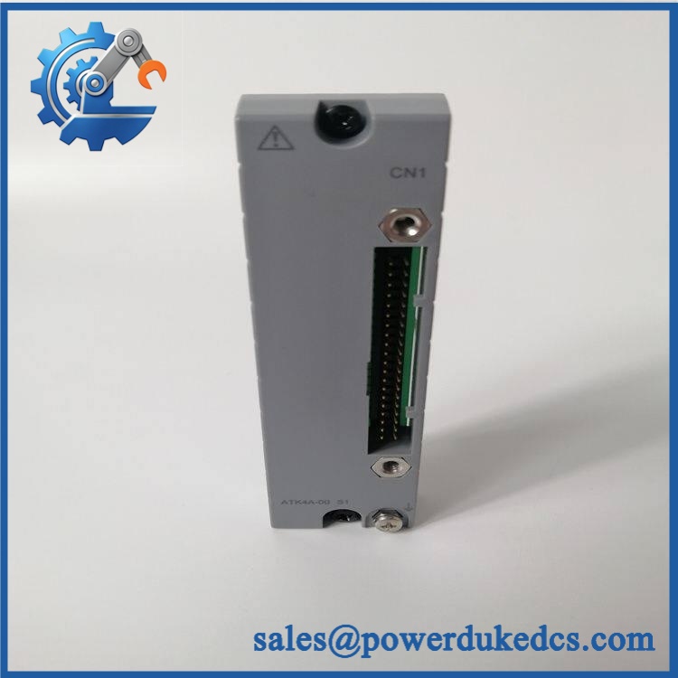
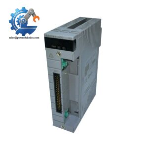
Yokogawa KS8-5*A
🚨 Common Error Codes & Diagnostic Symptoms
Symptom/Code: FIO channel communication or signal loss after cable movement
→ Diagnosis: Open conductor, intermittent contact, or damaged connector caused by cable or pin failure
→ Action: Perform end-to-end continuity testing and replace the KS8 assembly if intermittent behavior is confirmed.
Symptom/Code: Multiple adjacent channels fail simultaneously
→ Diagnosis: A common interconnection path may have an open, short, or incorrect pin assignment
→ Action: Verify the complete 50-50 pin mapping and connector seating; replace the cable if the assembly fails pinout testing.
Symptom/Code: Channel instability after maintenance
→ Diagnosis: Partially seated connector, bent contact, contamination, or Style mismatch
→ Action: Isolate the circuit, inspect both mating connectors, verify the exact KS8 suffix, and replace the cable where physical damage is present.
This cable does not contain diagnostic firmware, so there are no native KS8 error codes. Troubleshooting is primarily based on continuity, pinout, connector condition, and resulting FIO channel behavior.
🚨 Cross-Reference & Lifecycle Migration
Lifecycle Status: Legacy / Limited availability.
The exact remains identifiable in specialist inventory records, including one listing showing a 10–12 week estimated lead time and another listing showing available stock. However, Yokogawa’s published KS8 documentation specifies as the documented Style B configuration. Trade records also explicitly identify A as replaced by B.
Replacement assessment:
- A → A: Direct like-for-like replacement.
- A → B: Verify before substitution. The newer documented suffix should not be treated as an automatic drop-in.
- Firmware flashing: Not applicable. This is a passive cable assembly.
- Hardware modification: Normally unnecessary for an identical replacement.
- Buffer-stock strategy: Plants operating Style A installations should maintain at least one verified spare where cable failure can interrupt a critical FIO channel. For new projects, engineering should confirm whether the current Style B cable is required. (Do not mix suffixes solely because both are 5 m cables.)
Field Engineer’s Tech Notes
First warning: do not focus only on cable length. A junior engineer may see two 5 m cables and assume they are interchangeable. The connector style, pin arrangement, and mating hardware determine whether the assembly is actually suitable. Current Yokogawa documentation identifies B, while the requested part is A.
Second warning: never skip the pin-to-pin test. On a 50-50 pin cable, one transposed or shorted conductor can create several misleading FIO symptoms. Before energizing the system, test every conductor, check for conductor-to-shield shorts, and inspect both connector faces under magnification. (This catches faults that a basic visual inspection misses.)
Strict QA & Testing SOP
- Inbound identification: Verify Yokogawa markings, complete designation, packaging labels, and physical quantity.
- Physical inspection: Check both connector bodies, pins, backshells, strain reliefs, cable jacket, and evidence of corrosion or mechanical stress.
- Length verification: Measure the finished assembly and record the result against the 5 m nominal specification.
- 100% continuity test: Check every conductor from connector A to the corresponding pin on connector B.
- Pinout verification: Compare the complete pin map against the approved wiring documentation.
- Short-circuit screening: Test conductor-to-conductor and conductor-to-shield isolation as applicable to the cable design.
- Shield continuity: Verify shield continuity and termination where specified by the assembly.
- Connector contact inspection: Look for bent, recessed, oxidized, loose, or contaminated contacts.
- Flex/intermittent test: Apply controlled movement to the cable near both connector ends while monitoring continuity.
- FIO integration test: Where a suitable Yokogawa test setup is available, connect the cable and confirm representative signal transfer through the connected FIO hardware.
- Thermal-condition review: Confirm the storage and installation environment remains within the documented -20 to 70 °C range.
- Final QC release: Record measured length, pinout results, continuity results, photographs, inspector approval, and packaging condition.
- Anti-static packaging: Protect connectors and cable ends against impact, contamination, and ESD exposure during shipment.
- Test evidence: Test videos are available for applicable inspection and functional checks upon request.
Buyer’s FAQ
Q1. Can I hot-swap a *A while the Yokogawa FIO system is running?
A: Treat the cable as a field wiring component, not a hot-swappable electronic module. Follow the site’s approved isolation procedure before disconnecting it. Removing a live FIO interconnect can create signal faults or unintended process indications.
Q2. How do I know a New Original *A is actually the correct cable?
A: Check the complete designation, 50-50 pin connector configuration, nominal 5 m length, physical connector construction, and actual-unit labeling. Do not accept a *B as an equivalent without engineering approval. Current Yokogawa documentation uses the *B designation.
Q3. Is this cable firmware-dependent?
A: No. *A is a passive signal cable. There is no firmware to flash. Compatibility depends on the physical interface, pinout, connector style, cable length, and connected FIO equipment.
Q4. What should I check before replacing it with *B?
A: Compare the connector style and mating hardware first. Yokogawa’s current documentation specifies , while older supplier records identify . The lifecycle relationship does not by itself prove a universal drop-in interchange.
Q5. What warranty should procurement require?
A: Request a written warranty covering manufacturing defects, connector defects, continuity failures, and DOA conditions, with a defined inspection period and return procedure. For legacy stock, require actual-unit photographs and documented continuity/pinout test results before shipment.



 Start Chat


