

Description
- Model: EC401-50 S3
- Brand: Yokogawa
- Series: EC401 ESB Bus Coupler for N-IO/FIO
- Part Type: 1-port ESB bus coupler module
- Core Function: Provides the ESB communication interface between a Yokogawa Field Control Unit and connected Node Units.
- Key Specs: 128 Mbps I/O data transmission; maximum 10 m ESB transmission distance; 0.5 A current consumption
- Connectable Units: Up to 9 ANB/ANT-series node units
- Redundancy: Supports dual-redundant ESB bus architecture
- FCU Slots: Slot 7 for non-redundant operation; slots 7 and 8 for dual redundancy
- Processor Compatibility: S3 or later required with CP471
- Suffix: -50 standard type, no explosion protection; S3 style revision
- Condition: New Original / New Surplus / Tested Refurbished — verify physical stock before PO
Yokogawa’s specifications identify EC401 as a 1-port ESB Bus Coupler Module for N-IO/FIO, with 128 Mbps I/O data transmission and up to nine connectable node units.
Product Introduction
Within a CENTUM VP FIO architecture, the EC401-50 S3 occupies the Field Control Unit’s dedicated ESB bus-coupler position and provides the communication path toward connected Node Units. The module transfers I/O data at 128 Mbps, supports an ESB transmission distance of up to 10 meters, and draws approximately 0.5 A. In a dual-redundant arrangement, two EC401 modules are installed in FCU slots 7 and 8.
For maintenance teams, the S3 style code is particularly important. Yokogawa states that EC401 style S3 or later is required when the module is used with a CP471 processor. The module can also connect up to nine supported ANB10S, ANB10D, ANT401, ANT411, or ANT421 units. (That makes the suffix a compatibility control point, not merely a revision label.)
Core Technical Specifications
| Parameter | Value |
|---|---|
| Model | EC401-50 S3 |
| Manufacturer | Yokogawa Electric Corporation |
| Product Type | ESB Bus Coupler Module |
| Application | N-IO / FIO |
| ESB Ports | 1 |
| ESB Interface Function | FCU-to-Node Unit communication |
| I/O Data Transmission Speed | 128 Mbps |
| Maximum Transmission Distance | 10 m |
| Maximum Connectable Units | 9 |
| Current Consumption | 0.5 A |
| Redundant Operation | Supported |
| Non-Redundant Slot | FCU slot 7 |
| Dual-Redundant Slots | FCU slots 7 and 8 |
| Compatible Node Units | ANB10S, ANB10D, ANT401, ANT411, ANT421 |
| CP471 Compatibility | S3 or later |
| SEM Requirement | Style 2 or later for SEM over Vnet/IP |
| Suffix -5 | Standard type, no explosion protection |
| Suffix -0 | Basic type |
| Approx. Weight | 0.2–0.24 kg |
The published specifications agree on 128 Mbps transmission, 10 m maximum transmission distance, approximately 0.5 A current consumption, and nine maximum connectable units. Minor weight differences in secondary listings appear to depend on how the module is weighed or documented.
Application Scenarios & Pain Points
A failed ESB coupler can make healthy downstream I/O nodes appear unavailable to the controller. In field troubleshooting, that distinction matters: replacing an individual I/O card will not correct an FCU-to-node communication failure caused by the bus coupler.
- Oil and gas: Distributed FIO nodes can connect through the to the FCU, with up to 9 supported node units on the documented ESB interface.
- Refining: Dual-redundant ESB arrangements place modules in both FCU slots 7 and 8, reducing exposure to a single coupler failure.
- Chemical processing: Where cabinets approach 50°C+ ambient conditions, verify the complete FCU installation environment and thermal loading rather than evaluating the coupler independently.
- Power generation: A tested S3 coupler can preserve a CP471-based FCU architecture without forcing an unnecessary controller migration.
- Utilities: The 128 Mbps ESB data path provides the communication backbone for distributed analog and digital I/O nodes.
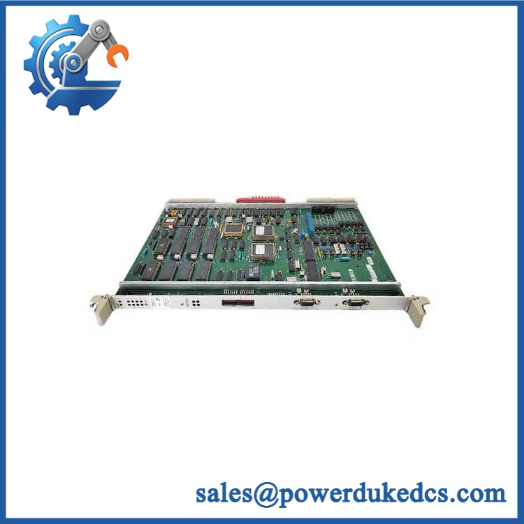
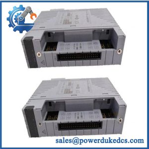
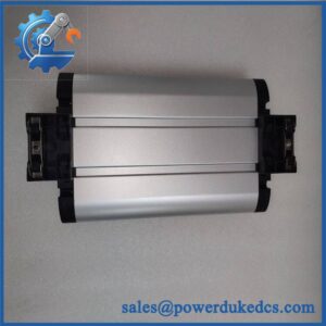
Yokogawa EC401-50 S3
🚨 Common Error Codes & Diagnostic Symptoms
Symptom/Code: ESB node communication lost / multiple downstream I/O nodes offline
→ Diagnosis: A common failure across several connected Node Units points toward the , ESB cabling, node power, or FCU interface rather than simultaneous I/O-card failures.
→ Action: Check ESB status and redundant path availability; replace the -50 S3 after confirming the bus and node power are healthy.
Symptom/Code: CP471 processor does not establish expected ESB communication
→ Diagnosis: An older style may be incompatible with CP471. Yokogawa specifically requires style S3 or later for operation.
→ Action: Verify the style marking; replace with an S3-or-later unit where required.
Symptom/Code: Redundant ESB path degraded
→ Diagnosis: One of the two modules or its associated ESB path may have failed, leaving the FCU operating without full bus redundancy.
→ Action: Inspect slots 7 and 8, bus connections, and status diagnostics; restore the failed path before the next planned maintenance window.
🚨 Cross-Reference & Lifecycle Migration
- Lifecycle Status: Legacy / lifecycle-controlled spare for existing CENTUM VP FIO installations. Current documentation remains available from Yokogawa, while supplier records continue to identify -50 S3 as a stocked legacy spare.
- Base Product: — 1-port ESB Bus Coupler Module for N-IO/FIO.
- Critical Revision: S3 or later is required with . This is the most important cross-reference condition for processor migration.
- Older Style Risk: An earlier style should not be substituted into a installation merely because the base model number matches.
- Redundancy: Non-redundant operation uses slot 7; dual-redundant operation uses matching modules in slots 7 and 8.
- Supported Nodes: ANB10S, ANB10D, ANT401, ANT411, and ANT421 are listed as connectable units.
- Firmware Flash: No generic firmware-flash requirement is established for a like-for-like replacement. The engineering review should focus on style code, FCU processor compatibility, redundancy, and system release.
- Migration Strategy: Where CP461-to- migration is planned, Yokogawa requires style S3 or later. Yokogawa also states that CP461 and cannot coexist in a dual-redundant pair, and that CP461-to- replacement must follow its prescribed service procedure.
- Buffer Stock: For a critical FIO cabinet, maintain at least one verified S3 spare, with additional units for geographically isolated sites or extended shutdown exposure.
Field Engineer’s Tech Notes
Warning 1 — Check the style marking before installation, especially with .
I would not approve an replacement from the base number alone. Yokogawa explicitly requires S3 or later for . A visually identical older-style coupler can power up yet still be the wrong procurement choice.
Warning 2 — Never treat slot 7/8 placement as optional in a redundant FCU.
For a non-redundant bus, belongs in slot 7 and slot 8 is covered with a dummy module. In a dual-redundant arrangement, matching couplers occupy both slots. Moving a module without confirming the redundancy design can leave the node degraded or unavailable.
Also check the ESB cable length. The documented maximum direct transmission distance is 10 m; do not assume an arbitrary longer cable run will maintain the specified bus performance.
Strict QA & Testing SOP
Step 1 — Inbound Inspection
- Verify Yokogawa -50 S3 on the physical label.
- Record serial number, style code, date information, and hardware revision.
- Perform OEM anti-counterfeit visual inspection.
- Photograph the complete nameplate and connector surfaces.
Step 2 — Mechanical Inspection
- Examine the enclosure and front-panel hardware.
- Inspect the ESB connector for bent, recessed, contaminated, or oxidized contacts.
- Check mounting hardware and card guides.
- Confirm no evidence of overheating, corrosion, impact, or unauthorized repair.
Step 3 — Electrical Checks
- Verify supply conditions in the approved test rack.
- Check grounding where applicable.
- Confirm expected current consumption behavior around the documented 0.5 A operating value.
Step 4 — Live Rig Testing
- Install the module in a compatible Yokogawa FCU test environment.
- Use slot 7 for a non-redundant test or slots 7 and 8 for a redundant test.
- Power the FCU and confirm module recognition.
- Establish ESB communication with a compatible Node Unit.
Step 5 — Communication Test
- Verify stable 128 Mbps ESB I/O data communication.
- Exercise representative I/O traffic.
- Monitor diagnostic counters and communication stability.
- Confirm operation across the documented configuration distance where the test fixture supports it.
Step 6 — Redundancy Test
- Install and S3 in the paired redundant slot.
- Verify both ESB paths are recognized.
- Simulate failure of one bus-coupler path under controlled conditions.
- Confirm the remaining path maintains required communication.
- Restore the failed path and verify recovery.
Step 7 — Compatibility Test
- Where the spare is intended for a system, verify the S3 style marking before testing.
- Confirm processor-to- communication.
- Review system diagnostics for compatibility alarms.
- Record the processor and coupler revisions used during the test.
Step 8 — Extended Stability
- Run representative I/O traffic for an extended period.
- Monitor communication status, current draw, module temperature, and diagnostic state.
- Cycle the approved redundant path where applicable.
Step 9 — Final QC
- Record serial number, style code, test-rack configuration, and measured results.
- Issue a signed QC/Test Report.
- Apply a QC Passed label.
- Package with ESD protection and connector protection.
Test evidence: Test videos, nameplate photographs, and the serial-number-specific QC report should be available for procurement review before shipment.
Buyer’s FAQ
Q1. Can I hot-she S3?
Do not treat hot replacement as automatically permitted simply because the system has redundant ESB paths. Confirm the installed FCU configuration, redundancy state, system procedures, and process impact before removing the module. The safer assumption is that a live swap requires an approved site procedure.
Q2. How do I verify that a “New Orl” S3 is the correct revision?
Ask for a clear photograph of the physical component tag showing and the style information. For systems, the critical requirement is S3 or later.
Q3. What is the real compatibility check when reng S3?
Match the FCU processor, style, slot arrangement, ESB redundancy architecture, connected node types, and system release. Up to nine supported node units can be connected, but the bus topology must remain within the documented architecture.
Qes S3 require a firmware flash?
There is no blanket module-specific firmware requirement established for a like-for-like exchange. The critical check is hardware style and system compatibility, particularly S3-or-later compatibility with .
Q5. What should the warranty cover on us S3 stock?
The quotation should identify the exact model and style, serial number, condition, warranty duration, return process, and pre-shipment test scope. For this module, the acceptance package should document FCU recognition, ESB communication, redundancy behavior where applicable, and compatibility when required.



 Start Chat


