

Description
- Model: KS9-5*A
- Brand: Yokogawa
- Series: KS9 Signal Cable Series
- Part Type: DCS I/O Signal Cable
- Core Function: Carries multi-channel I/O signals between compatible Yokogawa system hardware and associated terminal hardware.
- Key Specs: 5 m class cable; 50-pin interface; passive signal connection; application-specific pin assignment.
- Procurement Note: The exact
KS9-5*Amarking should be verified against the installed cabinet documentation before PO release (suffix conventions can vary by Yokogawa ordering scheme).
Product Introduction
A damaged DCS cable can leave an entire I/O path unavailable even when the processor and I/O modules are operating normally. Yokogawa KS9-5*A belongs to the KS9 signal-cable family used for defined I/O interconnections, with the 5 m configuration intended for cabinet installations where fixed-length harnessing is required. In field deployments, the cable itself is often overlooked during troubleshooting; connector damage, intermittent conductors, or an incorrect pin assignment can produce symptoms that resemble an I/O module failure.
For legacy migration projects, retaining the original cable architecture can reduce cabinet rework and commissioning exposure. Yokogawa documentation identifies KS9 cables as 50-pin signal cables and provides defined length and style combinations. The exact *A configuration should therefore be checked against the physical label and system drawing before substitution (do not approve a cable on length alone).
Core Technical Specifications
| Parameter | Value |
|---|---|
| Manufacturer | Yokogawa |
| Model | KS9-5*A |
| Product Type | DCS I/O Signal Cable |
| Cable Family | KS9 |
| Nominal Length | 5 m class |
| Signal Interface | 50-pin |
| Electrical Nature | Passive signal interconnection |
| Firmware | Not applicable |
| Primary Compatibility Check | Connector, pin mapping, cable length, and Yokogawa I/O architecture |
| Lifecycle Position | Legacy / configuration-dependent |
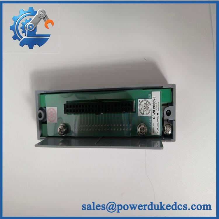
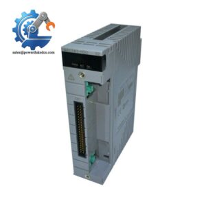
Yokogawa KS9-5*A
Application Scenarios & Pain Points
A cabinet restoration case: A replacement cable is needed after repeated connector handling has produced intermittent I/O faults. With a 5 m harness already specified by the cabinet design, using the correct KS9 configuration avoids unnecessary field rewiring and keeps the original termination arrangement intact.
In refinery control panels, engineers may encounter intermittent channel dropouts caused by contact resistance or conductor fatigue rather than a failed I/O card. At ambient temperatures above 50°C, repeated thermal expansion can make marginal connector faults more noticeable.
For power-generation DCS cabinets, an exact signal cable can shorten maintenance intervention because technicians can exchange the harness without modifying established terminal assignments. This is particularly useful where shutdown windows are measured in hours rather than days.
During legacy migration, retaining the existing KS9 path can simplify staged replacement work. The cable remains passive, so the engineering focus stays on the mating I/O and terminal interfaces rather than firmware conversion.
Without the correct harness, procurement may face an avoidable engineering change: custom cable fabrication, pin-by-pin validation, insulation testing, and a new wiring record. A matching factory cable removes much of that work.
🚨 Common Error Codes & Diagnostic Symptoms
Symptom/Code: Intermittent multiple-channel I/O faults
→ Diagnosis: Damaged conductor, oxidized connector contact, or poor mechanical retention can interrupt several signal paths simultaneously.
→ Action: Inspect both 50-pin connectors, perform pin-to-pin continuity testing, and replace the cable if intermittent resistance is confirmed.
Symptom/Code: Several channels fail simultaneously while the I/O module remains healthy
→ Diagnosis: A common cable conductor or connector-side fault is more likely than simultaneous electronic failure of multiple channels.
→ Action: Isolate the cable and test all applicable conductors against the Yokogawa wiring diagram; replace the harness when mapping or continuity is incorrect.
Symptom/Code: Signal appears normal during static test but drops during cabinet movement
→ Diagnosis: Internal conductor fatigue or strain-relief failure is producing an intermittent open circuit.
→ Action: Perform controlled flex testing near both connectors and replace the cable if signal integrity changes.
🚨 Cross-Reference & Lifecycle Migration
Lifecycle Status: Legacy / Configuration-Dependent. Treat this as a controlled spare rather than assuming routine factory availability.
Cross-reference caution: Yokogawa documentation for the KS9 family uses detailed ordering combinations for cable length and style. A commonly documented 5 m configuration is KS9-05*B; therefore, KS9-5*A should not be declared identical without checking the actual product label, connector style, and system drawing.
Previous or alternate revision: No universal direct cross-reference should be asserted from the base KS9 designation alone. The final suffix can define the physical or application configuration.
Firmware requirement: None for the cable itself. Compatibility is determined by hardware interface, pin assignment, shielding/grounding arrangement, and connected Yokogawa equipment.
Buffer-stock strategy: For a production-critical legacy cabinet, holding at least one verified spare cable per critical cable type is prudent. Cable failure can create disproportionate downtime relative to the purchase cost, particularly when the original harness configuration is difficult to reproduce locally.
Field Engineer’s Tech Notes — Anti-Pitfall Guide
First warning: never trust connector fit by itself. A 50-pin connector can physically mate while the signal mapping is wrong. Before energizing a replacement, compare the conductor mapping against the approved Yokogawa drawing and verify continuity pin by pin.
Second warning: protect the connector during installation. I have seen intermittent DCS faults caused by excessive bending directly behind the connector. Maintain the specified bend radius, avoid pulling on the cable body during insertion, and inspect the strain-relief area before returning the cabinet to service (ESD precautions still apply around the connected I/O electronics).
Strict QA & Testing SOP
Step 1 — Inbound Identification
Record the complete KS9-5*A marking, visible style/revision code, cable length, connector identification, manufacturer markings, and packaging condition.
Step 2 — OEM Visual Inspection
Inspect the jacket, labels, connector shells, locking hardware, strain reliefs, contact surfaces, and manufacturing marks. Look for cuts, crushed sections, corrosion, contamination, or unauthorized retermination.
Step 3 — Dimensional Verification
Measure the cable against the required nominal length and compare the measured value with the approved procurement specification.
Step 4 — Connector Inspection
Check every accessible contact for bending, contamination, recession, oxidation, or mechanical damage. Confirm that the mating hardware matches the intended Yokogawa equipment.
Step 5 — Pin-to-Pin Continuity Test
Test all applicable conductors with a calibrated cable tester. Record open circuits, shorts, intermittent contacts, and unexpected resistance.
Step 6 — Insulation Resistance Test
Perform an insulation test appropriate to the cable construction and connected-equipment requirements. Do not apply an unsuitable test voltage to connected electronics.
Step 7 — Shield / Ground Verification
Where the specific cable configuration includes shielding or drain conductors, verify continuity and termination against the applicable Yokogawa drawing.
Step 8 — Signal Mapping Verification
Compare connector pin assignment against the approved system schematic. This is the critical acceptance step for a multi-channel DCS harness.
Step 9 — Flex / Intermittent Test
Apply controlled movement near both connector strain-relief points while monitoring continuity. Any signal interruption is a rejection condition.
Step 10 — Final QC Record
Document part marking, measured length, connector condition, continuity results, insulation results, shield verification, and acceptance status.
Packaging: Use protective caps where applicable, prevent connector impact, and package the harness to avoid sharp bends during transportation. Test videos are available for procurement and engineering review.
Buyer’s FAQ — Dynamic Q&A
Q1. Can I hot-swap *A while the DCS cabinet is powered?
Do not treat the cable as hot-swappable just because it is passive. Disconnecting a live I/O harness can create unintended signal transitions, alarms, trips, or electrical transients. Follow the approved Yokogawa maintenance procedure and isolate the affected I/O before replacement.
Q2. How do I know this is a genuine original Yokogawa cable?
Require the original manufacturer marking, exact part identification, connector construction, correct cable length, and a documented pin-to-pin test. For legacy cable stock, physical inspection plus electrical verification is stronger evidence than packaging appearance alone.
Q3. My replacement says KS9 and is also 5 m. Is it automatically compatible?
No. The KS9 family contains configuration-specific ordering codes. Verify the complete suffix, connector style, pin mapping, shielding arrangement, and receiving Yokogawa hardware before approving the replacement.
Q4. Does *A require firmware flashing?
No. It is a passive cable. There is no firmware inside the cable; the relevant compatibility checks are electrical and mechanical.
Q5. What warranty should procurement request?
Require a written functional warranty covering conductor continuity, connector integrity, insulation performance, and correct signal mapping under the agreed acceptance conditions. The PO should also specify the RMA procedure and exclusions for field damage, unauthorized retermination, excessive bending, or incorrect mating hardware.



 Start Chat


