

Description
- Model: ATK4A-00 S1
- Brand: Yokogawa
- Series: CENTUM CS / CENTUM VP Field I/O
- Part Type: KS Cable Interface Adapter
- Core Function: Provides the physical interface between compatible Yokogawa FIO modules and external terminal boards through KS-series cabling.
- Key Specs: 16-channel interface, 40-pin MIL-type connector, KS1/KS2 cable compatibility, and direct connection to supported analog FIO modules. Yokogawa documentation identifies the base ATK4A-00 as a KS Cable Interface Adapter used with FIO modules such as AAI141, AAV141, and AAI841.
Product Introduction
A failed interface adapter can take a healthy Yokogawa FIO channel group offline even when the actual I/O electronics remain fully operational. The YOKOGAWA ATK4A-00 S1 is the connection hardware used to link compatible FIO modules to remote terminal boards through KS-series cables. Rather than performing signal computation itself, it handles the physical marshalling path between the I/O module and field termination hardware.
In field deployments, that distinction is important. This is an interface accessory, not a standalone analog input or output card. Yokogawa documentation specifically lists the ATK4A-00 option for 16-channel FIO modules and identifies it for connection to terminal boards such as the AEA4D through KS cabling.
Core Technical Specifications
| Parameter | Value |
|---|---|
| Manufacturer | Yokogawa Electric Corporation |
| Model | ATK4A-00 S1 |
| Base Model | ATK4A-00 |
| Product Type | KS Cable Interface Adapter |
| System Family | CENTUM CS / CENTUM VP FIO |
| Interface Function | FIO module to terminal-board connection |
| Channel Capacity | 16-channel interface |
| Cable Interface | KS-series cable |
| Cable Compatibility | KS1 / KS2, subject to the specific FIO/terminal-board combination |
| Connector | 40-pin high-density/MIL-type interface |
| Typical Compatible Modules | AAI141, AAV141, AAB141, AAI841 and other supported FIO modules |
| Typical Terminal Board | AEA4D and other Yokogawa terminal-board combinations specified for the installed I/O |
| Mounting | Directly mounted to compatible FIO module |
| Signal Processing | None; passive interface function |
| Typical Signal Path | FIO Module → ATK4A Adapter → KS Cable → Terminal Board |
| Base Documentation | Yokogawa CENTUM FIO specifications and connection documentation |
Yokogawa’s own specification documents confirm that /K4A00 denohe KS Cable Interface Adapter and show it as an option for several 16-channel FIO modules.
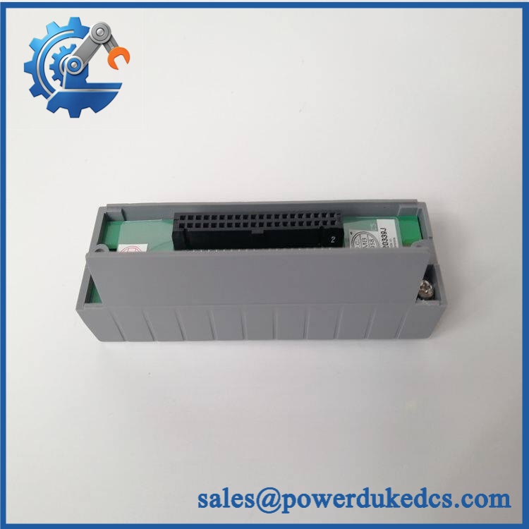
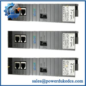
YOKOGAWA ATK4A-00 S1
Application Scenarios & Pain Points
A cabinet-level connection fault can be surprisingly difficult to diagnose when the underlying FIO module still passes its own diagnostics.he S1 sits directly in that signal path, so connector condition and cable matching deserve the same attention as the electronics.
CENTUM VP Analog I/O
For Yokogawa FIO systems, the adapter provides the physical route from supported I/O modules to remote terminal boards. Yokogawa specifically dots for modules including AAI141, AAV141, and AAI841.
CENTUM CS 3000 Brownfield Plants
Older installations often depend on established KS-cable marshalling arrangements. A damaged adapter may therefore become a plant-specific spare-parts issue even when replacement FIO modules remain available.
Petrochemical and Process Plants
In large marshalling cabinets, the use of standardized KS cable interfaces reduces the need for extensive point-to-point wiring. One incorrect adapter or cable can affect an entire group of field signals, so exact part-number matching matters.
Remote Terminal Board Installations
Where the terminal board is physically separated from the FIO node, the adapter provides the required cable interface. Yokogawa documentation idees specifically for connecting supported FIO modules to terminal boards such as AEA4D.
Harsh Industrial Environments
The S1 suffix is associated by current supplier documentation with a G3 conformal-coating option, but the exact environmental qualification of a particular assembly should be verified against the Yokogawa documentation for the installed configuration.
Common Error Codes & Diagnostic Symptoms
Because the S1 is an interface adapter rather than an intelligent controller, it does not have its own CPU fault-code system. Physical and channel-level symptoms are more meaningful.
Symptom/Code: Multiple Channels Lost Simultaneously
→ Diagnosis: A loose connector, damaged adapter contacts, incorrect KS cable, or poor mating between the adapter and FIO module can interrupt several signal paths at once.
→ Action: Inspect the adapter/cable chain and replhe S1 if the fault follows the adapter.
Symptom/Code: Intermittent Analog Readings
→ Diagnosis: Oxidized contacts, mechanical stress, damaged connector pins, or an intermittent KS cable may produce unstable field values while the FIO electronics remain healthy.
→ Action: Check the complete physical signal path and replace the adapter after external wiring has been ruled out.
Symptom/Code: Terminal Board Connection Failure
→ Diagnosis: Incorrect cable type, incompatible terminal-board pairing, or a damaged 40-pin interface can prevent proper field termination.
→ Action: Verify the Yokogawa connection drawing and substitute a knood S1. Yokogawa’s documentation defines the adapter as part of the specified FIO-to-terminal-board connection architecture.
Cross-Reference & Lifecycle Migration
The most important compatibility point is that S1 should not be selected fromATK4A family name alone.
Base part relationship:
Yokogawa documentation identifies as the KS Cable Interface Adapter. The S1 designation is a specific version/ordering configuration encountered in the spare-parts market. Verify the complete nameplate before substitution.
Supported module relationships:
Yokogawa documentatiows as an option for multiple 16-channel FIO modules, including AAI141, AAV141, AAB141, and AAI841. A related document identifies it for AAI543 and connection to the AEA4D terminal board.
Firmware:
No firmware flashing is required for the adapter itself. It is not a programmable CPU or intelligent I/O module. Firmware and system-version compatibility belong to the associated FIO electronics.
Drop-in replacement warning:
Do not assume that every variant is interchangeable across every FIO module. Pin assignment, module type, terminal board, KS cable, and ordering configuration must match the actual system design.
Lifecycle status:
Current market sources describe the S1 as a legacy/discontinued component, while suppliers continue to list new and surplus inventory. Because OEM lifecycle status can vary by regional catalog and system generation, procurement should confirm current Yokogawa support status before placing a major stocking order.
For a live CENTUM installation, this points toward a controlled buffer-stock strategy: maintain verified spares for critical FIO connection points, especially where the installed plant depends on older KS-cable marshalling.
Field Engineer’s Tech Notes
First warning: never force the 40-pin interface into position. The adapter mates directly with the FIO module, and bent or recessed contacts can create a large number of apparent channel failures at once. Inspect alignment under good lighting before applying pressure.
Second warning: do not condemn the adapter until the KS cable has been checked. A broken conductor or defective connector can create the same symptoms as aed S1. Check the module, adapter, cable, and terminal board as one physical signal path (especially when an entire channel group disappears together).
Strict QA & Testing SOP
1. Inbound inspection
Confirm YWA S1 markings, base model, revision/style information, connector condition, enclosure integrity, and visible manufacturing identifiers.
2. Nameplate and traceability check
Photograph the complete identification label. Record serial or production information where present and compare it against the purchase specification.
3. Mechanical inspection
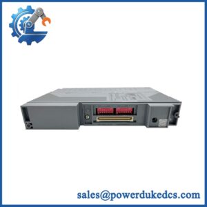
Inspect the 40-pin mating interface, mounting features, guides, locking hardware, and cable connector for bent pins, cracks, contamination, or deformation.
4. Known-good FIO mating test
Mount the adapter onto a compatible Yokogawa FIO module using the approved installation procedure. Confirm proper mechanical engagement without excessive insertion force.
5. KS cable test
Connect the specified KS-series cable and verify full connector engagement. Check cable continuity before introducing the assembly into an energized plant system.
6. Signal-path verification
Using a compatible test setup, exercise representative channels through the complete chain:
FIO m → S1 → KS cable → terminal board
Confirm that expected signal states reach the terminal-board side.
7. Multi-channel testing
Because the adapter is intended for a 16-channel interface, verify multiple channel paths rather than relying on a single continuity check.
8. Intermittency test
Under controlled conditions, inspect for signal dropout associated with connector movement, cable movement, or mechanical vibration. Any intermittent response should trigger further inspection.
9. Final QC release
Record test results, photographs, part number, condition, and technician approval.
10. ESD-safe packaging
Protect the connector and conductive interfaces against ESD and mechanical impact. Keep the adapter separated from loose metal hardware during shipment.
11. Evidence package
Provide the inspection record and functional-test report with the shipment. Test videos are available to document physical inspection, mating verification, and representative signal-path testing.
Buyer’s FAQ
Is S1 itself an I/O module?
A: No. It is a KS Cable Interface Adapter. The actual signal conversion and processing are performed by the attached Yokogawa FIO module. Yokogawts as an interface option for supported FIO modules.
Q: Can I hot-swap this adapter like a Yokogawa electronic I/O module?
A: Do not assume that. The adapter is a physical interface component, and removal can disturb field connections and the associated I/O module. Follow the approved Yokogawa maintenance procedure and site isolation requirements before removing it.
Q: How do I verify a “New Orl” S1?
A: Request clear photographs of the complete part marking, connector interface, manufacturing label, and packaging. For legacy Yokogawa hardware, also request a functional or continuity test record and verify that the supplied version matches the installed FIO configuration.
Q: Dhe S1 need firmware or configuration before installation?
A: No firmware is loaded into the adapter itself. It is passive interface hardware. The relevant compatibility checks concern the connected FIO module, KS cable, terminal board, and the CENTUM system configuration.



 Start Chat


