

Description
- Model: ANB10D-440
- Brand: Yokogawa
- Series: ANB10D ESB Bus Node Unit for FIO/N-IO
- Part Type: Dual-redundant ESB bus node interface unit
- Core Function: Interfaces field I/O modules with the Field Control Unit through the redundant ESB bus while supplying power to installed I/O modules.
- Key Specs: 24 VDC input; dual-redundant power architecture; maximum 8 I/O modules
- Mounting: 19-inch rack
- Power Consumption: 24 VDC, 5.5 A
- System Interface: Dual ESB bus through redundant SB401 modules
- Typical Configuration: Two PW481/PW482/PW484 power modules + two SB401 modules
- Approx. Weight: 10 kg with 8 I/O modules
- Lifecycle Status: Legacy / Stop-production variants reported; replacement path available
- Stock & Condition: New Original / New Surplus / Tested Refurbished — verify exact configuration before PO
Yokogawa’s official specification identifies ANB10D as the node unit for a dual-redundant ESB bus, with two power-supply modules and two SB401 ESB bus interface slave modules used for dual-redundant operation.
Product Introduction
The ANB10D-440 is installed between the FIO field-I/O layer and the Field Control Unit, carrying analog/contact I/O data across the ESB bus while distributing power to the node’s I/O modules. The ANB10D architecture supports up to eight I/O modules, and the dual-redundant version uses two power-supply modules and two SB401 bus-interface modules. For the -440 configuration, the documented supply is 24 VDC rather than 100–120 VAC or 220–240 VAC.
In field deployments, the exact suffix matters because ANB10D-440 identifies the 24 VDC power configuration, while connector units and expansion-license options are separately specified. Current secondary lifecycle records identify -440/CU2N/NDEL and -440/CU2T/NDEL as stopped-production configurations with replacements.;
Core Technical Specifications
| Parameter | Value |
|---|---|
| Model | -440 |
| Manufacturer | Yokogawa Electric Corporation |
| Product Type | ESB Bus Node Unit |
| ESB Architecture | Dual-redundant |
| Supply Voltage | 24 VDC |
| Supply Configuration | Dual-redundant power supply |
| Power Consumption | 5.5 A at 24 VDC |
| Power Modules | PW481, PW482, or PW484; two units for redundancy |
| ESB Interface Modules | SB401; two units for redundancy |
| Maximum I/O Modules | 8 |
| FCU Connection | ESB bus |
| Mounting | 19-inch rack |
| Mounting Hardware | 4 × M5 screws |
| Overall Width | 482.6 mm |
| Rack Width | 440 mm mounting dimension |
| Height | 221.5 mm |
| Depth | 205 mm |
| Approx. Weight | 10 kg including 8 I/O modules |
Yokogawa specifies the dimensions at 482.6 × 221.5 × 205 mm, with four M5 rack-mount holes. Its published electrical data gives 5.5 A at 24 VDC and approximately 10 kg including eight I/O modules.
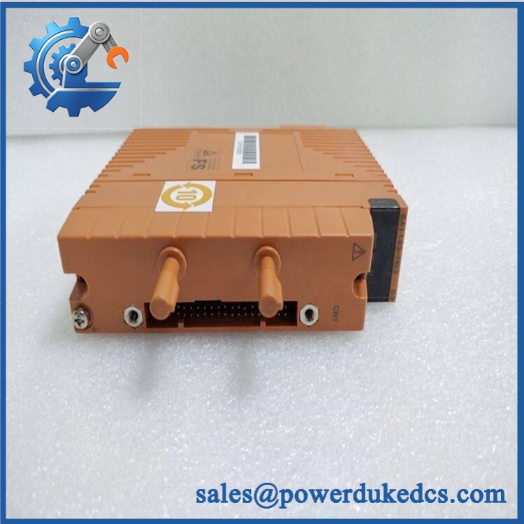
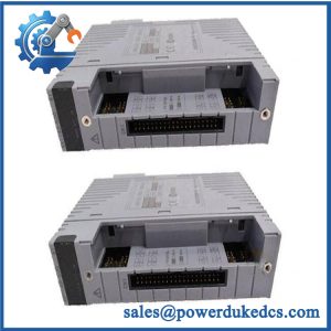
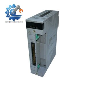
Yokogawa ANB10D-440
Application Scenarios & Pain Points
A node failure can affect an entire group of field I/O modules even when the individual I/O cards are healthy. That is the central maintenance concern with -440: the unit provides both the ESB network interface and node-level power distribution.
- Oil and gas: FIO nodes can collect process measurements from transmitters and contacts while the maintains communication with the FCU. In cabinets operating around 50°C ambient, verify the applicable installation limits and node loading before replacing or expanding the assembly. Yokogawa specifically notes installation limitations related to node loading and cabinet temperature.
- Refining: Dual-redundant SB401 communication paths and redundant power modules can support continuity of the I/O node during a single equipment failure.
- Chemical plants: Distributed field instrumentation can remain connected through a centralized ESB node, reducing the need to relocate existing field wiring during a maintenance event.
- Power generation: A tested replacement node can preserve the existing FIO cabinet arrangement and avoid an unplanned redesign of the FCU-to-I/O architecture.
- Utilities and water treatment: The eight-slot capacity allows multiple communication and I/O modules to be concentrated in one rack-mounted node.
🚨 Common Error Codes & Diagnostic Symptoms
Symptom/Code: ESB communication lost / node disappears from FCU diagnostics
→ Diagnosis: Possible failure of one or both ESB interface modules, loss of node power, damaged ESB connection, or an associated FCU-side communication fault.
→ Action: Check redundant ESB paths and node power first; replace the failed assembly or associated only after isolation testing.
Symptom/Code: Multiple I/O modules simultaneously report communication or power faults
→ Diagnosis: A node-level power-distribution fault is more likely than simultaneous failures of independent I/O cards. Verify the PW481/PW482/PW484 supply modules and the 24 VDC source.
→ Action: Check both redundant power paths; replace the faulty power module or node component as identified.
Symptom/Code: Redundant node operates in degraded state
→ Diagnosis: One redundant power or ESB communication path may be unavailable, leaving the node functioning without full redundancy.
→ Action: Inspect status, power-module status, connectors, and ESB cabling; restore the redundant path before the next maintenance window.
Yokogawa’s configuration explicitly uses two power modules and two modules in a dual-redundant installation, making simultaneous node-level symptoms an important diagnostic clue.
🚨 Cross-Reference & Lifecycle Migration
- Lifecycle Status: Legacy / Stop Production for documented -440 configurations. Current secondary records explicitly identify -440/CU2N/NDE/CU2T/NDEL as stopped-production versions.
- Primary Replacement Path: is identified by current supplier lifecycle records as the newer replacement for the correspo configurations.
- Power Code: -440 = dual-redundant power supply + 24 VDC + basic type without explosion protection under Yokogawa’s suffix structure.
- Connector Variants:
/CU2Nuses the ESB-bus connector unit;/CU2Tuses the ESB-bus connector unit with terminators. These are not interchangeable procurement descriptions. - Node Expansion:
/NDELis a software license for node expansion in the documented ordering structure. - Older-System Compatibility: Yokogawa states that existing ANB10x-x xx/NDEL units for CENTUM VP R5 or earlier can be used with CENTUM VP R6.01 or later, subject to the stated system conditions.
- Firmware Flash: No universal firmware-flash requirement is established for a like-for-like node replacement. System release and installed module configuration should still be verified.
- Buffer Stock Strategy: Treat the -440 as a lifecycle spare. For a critical FIO node, keep a complete tested node or the critical redundant components available rather than waiting for a failure.
A crucial procurement point: is not a complete configuration description for every commercial ordering situation. The exact connector and software option may be /CU2N, /CU2T, /NDEL, or another combination. Verify the nameplate and BOM before PO approval.
Field Engineer’s Tech Notes
Warning 1 — Do not pull the wrong module during a live maintenance job.
The can contain two power modules and two ESB interface modules for redundancy. A node that appears healthy may already be operating on only one path. Confirm the redundancy state before removing any power or interface module. Yokogawa explicitly documents the dual-module architecture.
Warning 2 — Check the complete suffix before calling a replacement “identical.”
The -440 establishes the 24 VDC, dual-redundant, basic configuration, but connector and licensing options are separate. A /CU2N/NDEL node and a /CU2T/NDEL node can require different connector arrangements. Match the whole ordering configuration, not jus prefix.
During cabinet work, also protect the ESB connectors from contamination and mechanical stress. Connector damage can create intermittent communication faults that mimic a defective .
Strict QA & Testing SOP
Step 1 — Inbound Checks
- Confirm Yok on the physical nameplate.
- Record serial number, hardware revision, date code, and all visible suffix/options.
- Verify whether
/CU2N,/CU2T,/NDEL, or another option is fitted. - Photograph the complete assembly and connector units.
- Perform OEM marking and anti-counterfeit inspection.
Step 2 — Mechanical Inspection
- Check the 19-inch rack frame for deformation.
- Inspect all module slots and retaining hardware.
- Examine ESB connectors for bent contacts, contamination, oxidation, or mechanical damage.
- Check power terminals and M4 screw connections.
Step 3 — Power-System Inspection
- Verify the 24 VDC source.
- Inspect both redundant power-module positions.
- Check PW481/PW482/PW484 modules where fitted.
- Verify polarity and protective grounding.
- Confirm there is no abnormal short circuit before energization.
Step 4 — Live Rig Testing
- Install the node in a compatible Yokogawa FIO test environment.
- Power both redundant paths.
- Confirm normal startup and status indications.
- Verify FCU-to-node ESB communication.
- Confirm recognition of the installed I/O modules.
Step 5 — Redundancy Testing
- Establish dual-redundant operation.
- Simulate loss of one power path.
- Verify continued node operation on the remaining path.
- Restore the failed path and confirm recovery.
- Repeat the process for the redundant ESB communication path using an approved test procedure.
Step 6 — I/O Module Testing
- Populate representative supported I/O modules.
- Verify module recognition.
- Exercise digital and analog channels as applicable.
- Monitor the node for communication errors during simultaneous I/O activity.
- Confirm stable data exchange with the FCU.
Step 7 — Load and Thermal Testing
- Operate the node with a representative module population.
- Monitor 24 VDC current, node temperature, communication status, and supply stability.
- Yokogawa documents installation limitations related to node quantity and cabinet temperature; test conditions should therefore remain within the applicable installation specification.
Step 8 — Final QC Release
- Record all electrical and communication measurements.
- Confirm redundancy recovery behavior.
- Record serial number and hardware revision.
- Issue a signed QC/Test Report.
- Apply a QC Passed label.
- Protect all ESB and power connectors during anti-static packaging.
Test evidence: Test videos, configuration photographs, and the serial-number-specific QC report should be available for procurement review before shipment.
Buyer’s FAQ
Q1. Can I hot-swa?
Do not assume that the complete node can simply be removed under power. Although the architecture supports redundant power and ESB interface modules, the acceptable maintenance procedure depends on the installed cabinet, FCU configuration, and site operating procedure. Confirm redundancy status before disturbing the node.
Q2. I only” on my purchase request. Is that enough?
For preliminary identification, yes. For a PO, no. Yokogawa’s configuration includes connector and software options, and current replacement records distinguish //NDEL from //NDEL. Request the complete nameplate string or cabinet BOM.
Q still available as a normal current product?
Treat it as a legacy procurement item. Current secondary lifecycle records identify spe configurations as stopped production and point to as the replacement.
Q4. Does the replacement require firmware flashing?
There is no blanket firmware-flash requirement for a like-for-like node replacement. The engineering team should verify the installed CENTUM VP/FIO release, node configuration, installed I/O modules, ESB interface arrangement, and any applicable migration requirements. Yokogawa specifically notes compatibility of existing /NDEL node units from CENTUM VP R5 or earlier with CENTUM VP R6.01 or later.
Q5. What should the warranty cover on a New Original or su?
The quotation should identify the exact suffix/options, serial number, physical condition, warranty period, return procedure, and pre-shipment test scope. For a redundant ESB node, the acceptance package should include power-path testing, ESB communication verification, representative I/O communication, and redundancy testing rather than a visual inspection alone.



 Start Chat


