Description
- Brand: Foxboro
- Full Model Number: CM902WL
- System/Series Family: Foxboro I/A Series Industrial Power Module 2; CM900 Series
- Core Function: Converts selected AC input power into a regulated DC output for compatible industrial control equipment.
- Top 3 Technical Specifications:
- AC Input: Selectable 100 / 120 / 220 / 240 VAC; verify the nameplate and input-selection arrangement on the supplied unit.
- DC Output: 39 VDC at 1.7 A continuous, approximately 66.3 W.
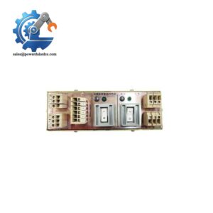
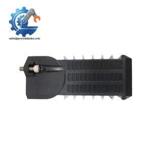
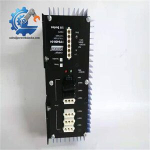
- Physical Features: Rear heat sink and two front status indicators, according to available product descriptions.
- Stock Status: Quote-confirmed by lot; condition options may include New Surplus or Tested Used, subject to actual inventory and inspection records.
Technical Product Introduction
Unexpected power-module failure can interrupt control-system operation even when the processor, I/O modules, and field wiring remain serviceable. The Foxboro CM902WL is identified as an I/A Series Industrial Power Module 2, associated with the CM900 family and the Astec AA16560 power-supply model. Its documented output rating is 39 VDC at 1.7 A continuous. For maintenance engineers supporting legacy process-control cabinets, the key requirement is matching the installed module’s input configuration, output requirements, and physical connections before exchanging the unit.
At 39 VDC and 1.7 A, the module has a nominal continuous output capacity of approximately 66.3 W. That figure provides a practical starting point for checking the load budget, but it does not establish the allowable load for every installation. Confirm the original module’s nameplate, wiring diagram, and cabinet power requirements before making a replacement decision. Compared with replacing an entire power assembly or redesigning an existing cabinet, an exact-match module replacement may reduce intervention time and avoid unnecessary changes to established wiring (provided the original configuration remains unchanged). Input selection, ventilation, and power distribution remain installation-specific.
Application Scenarios & Field Realities
- Legacy DCS power restoration: When a power-supply fault takes an I/A Series control assembly offline, verify the CM902WL part number and output rating before replacing the unit. A matching replacement may restore the existing power arrangement without changing the controller configuration.
- Process-control cabinet maintenance: In refineries and chemical plants, heat accumulation around power modules can shorten component service life. Inspect the rear heat sink, maintain adequate cabinet ventilation, and investigate recurring power faults rather than replacing modules without checking their operating conditions.
- Spare-parts inventory planning: For facilities operating aging I/A Series installations, retaining a verified CM902WL spare can reduce exposure to long procurement lead times. Record the module variant, input configuration, inspection history, and storage conditions so the replacement is ready for an outage.
- Power-system troubleshooting: If multiple control components lose power at the same time, verify the incoming AC supply, protective devices, output voltage, and connected load before declaring the CM902WL defective. A failed upstream supply or overloaded circuit can produce symptoms similar to a failed power module.
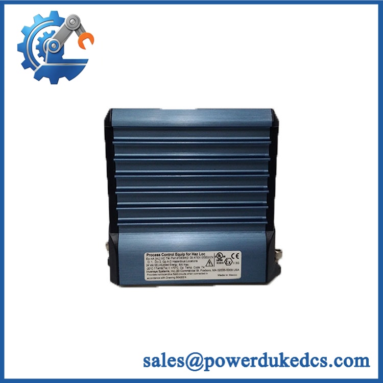
Foxboro CM902WL
Migration Compatibility and Installation Traps
Replacement Matrix
| Compatibility Check | Engineering Assessment |
|---|---|
| Exact-model replacement | Conditional drop-in replacement when the part number, hardware revision, electrical ratings, and connections match |
| Software compatibility | No software change is normally required for an equivalent power-supply replacement |
| Hardware modification | Not expected for an exact-match replacement; connector, mounting, or wiring changes require engineering review |
| Electrical compatibility | Verify the required AC input selection and the 39 VDC output rating against the installed configuration |
| CM902WL-B variant | Confirm the suffix and nameplate details; do not assume every listed variant is identical |
| Replacement of another CM900 model | Requires a documented electrical and mechanical compatibility check |
Field Traps to Watch Out For
Incorrect AC input selection: Product descriptions identify selectable 100, 120, 220, and 240 VAC input configurations. Before energizing a replacement, confirm the actual nameplate, input-selector arrangement, and plant supply voltage. Never assume that the previous module’s selector setting is correct for a replacement received from a different source.
Output loading and cabinet temperature: The 39 VDC, 1.7 A continuous rating corresponds to approximately 66.3 W of nominal output power. Check the connected load against the applicable OEM limits, and inspect the cabinet ventilation and heat-sink clearance. Operating near the rated capacity under elevated ambient temperatures requires particular attention to the manufacturer’s derating requirements.
Controlled replacement procedure: Isolate the equipment according to the plant’s electrical safety procedures, verify the absence of hazardous voltage, and document the existing wiring before removal. After installation, measure the DC output before reconnecting or enabling downstream equipment, following the approved commissioning procedure.
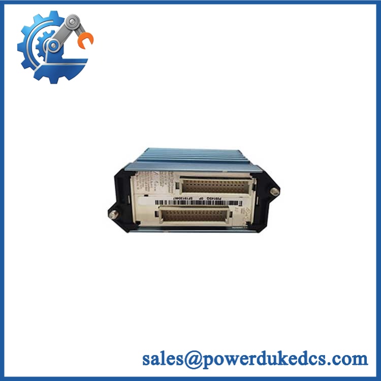
Foxboro CM902WL
Quality Assurance SOP
Every Foxboro offered for shipment should undergo documented inspection and electrical checks appropriate to its condition and the available OEM specifications. Testing must not exceed the manufacturer’s permitted limits.
Identity and physical inspection
- Compare the model number, revision markings, nameplate data, and visible product identifiers against the purchase specification.
- Perform an OEM anti-counterfeit visual inspection covering label consistency, enclosure markings, connector construction, fasteners, and visible workmanship. Visual inspection alone cannot prove authenticity.
- Inspect the enclosure, rear heat sink, input and output connections, and mounting features for impact damage, corrosion, contamination, or unauthorized modification.
- Check both front status indicators for physical damage and confirm their functions against available product documentation.
- Record the supplied unit’s condition as New Surplus, Used, or Refurbished, as applicable. Do not describe a previously used unit as factory-new.
Electrical inspection and functional testing
- Verify the input configuration and inspect the input terminals before applying power.
- Measure the AC input using an appropriately rated instrument and controlled test setup.
- Energize the module under the specified input conditions and measure its DC output against the applicable acceptance limits.
- Conduct a controlled load test where suitable equipment and the applicable load limits are available. Confirm stable output without exceeding the rated continuous current.
- Monitor the unit for abnormal heating, unusual noise, visible damage, or unexpected output variation during the approved test period.
- Record the measured input and output values, load conditions, inspection findings, and test results for the shipment file.
System-level verification
- Confirm that the output remains within the applicable OEM limits under the intended operating load.
- Where the installed control system is available, verify that downstream equipment receives the required supply and returns to its expected operating state.
- Check the relevant system alarms and module indicators using the applicable installation documentation. Do not assume that the power module uses the same ERR/RUN indicator logic as a processor or I/O module.
- Perform a communication handshake test only at the relevant downstream controller or communication interface. The is a power module, not a communications processor; a protocol test on the power module itself is not applicable.
- Record the final inspection status and package the unit to protect its connectors, enclosure, and heat-sink assembly during transport.
Procurement release criterion: Release the for shipment only after its identity, visible condition, input configuration, output performance, and inspection results have been documented. For field replacements, the receiving engineering team should compare those records with the installed module’s nameplate and approved electrical drawings before installation.