Description
- Brand: Foxboro
- Full Model Number: E69F-T-I2-JRS
- System/Series Family: Foxboro E69F Field-Mounted Current-to-Pneumatic Converter Series
- Core Function: Converts an electrical DC current input into a proportional pneumatic pressure signal for pneumatic actuators, control valves, and other process instruments.
- Top 3 Technical Specifications:
- Input Signal: 4–20 mA DC; selectable split ranges of 4–12 mA or 12–20 mA; nominal input impedance 170 ohms.
- Output Signal: 20–100 kPa (3–15 psi or 0.2–1.0 bar), according to output code 2.
- Enclosure and Accessories: Threaded explosionproof cover, integral explosionproof junction box, adjustable filter regulator without gauge, and supply/output gauges.
- Lifecycle Status: Legacy product; supplier references report discontinuation. Confirm current OEM lifecycle status before procurement.
- Stock Status: Subject to physical inventory verification.
- Available Condition: New Original, New Surplus, or Tested Used, according to actual stock.
- Replacement Requirement: Verify input range, direct/reverse action, output pressure range, hazardous-area approval, and pneumatic connections.
- Warranty: Coverage and duration specified in the sales quotation.
Migration, Compatibility & Installation Traps
Replacement Compatibility Matrix
| Replacement Category | Engineering Assessment |
|---|---|
| Drop-in Replacement | Conditional. An identical E69F configuration may be suitable when the complete model code, input range, output range, action, mounting, pneumatic connections, and certifications match. |
| Software Compatible | Not applicable to the converter itself. The E69F is a field instrument with no independent firmware or DCS software package. The host controller’s analog-output scaling must match the converter’s input configuration. |
| Hardware Modification Required | Potentially. An alternative instrument may require changes to mounting brackets, electrical connections, air tubing, pressure range, or hazardous-area installation provisions. |
| Replacement with a Modern I/P Converter | Requires engineering review. Verify input impedance, output pressure, action, supply-air requirements, response characteristics, environmental protection, and area certifications. |
| Migration to a Digital Valve Positioner | Not a direct substitution. Assess feedback requirements, actuator compatibility, control strategy, configuration, diagnostic integration, and commissioning requirements. |
Field Traps to Avoid
Input range and output-action mismatch
The E69F input can be configured for full-range 4–20 mA or split-range operation. Direct or reverse action must also match the specified application. Before installation, inspect the original instrument settings and the approved loop documentation.
A replacement configured for the wrong input range may reach its minimum or maximum pneumatic output prematurely. Verify the response at multiple input points rather than relying on a single zero or span check.
Hazardous-area enclosure and junction-box requirements
The T enclosure code identifies a threaded explosionproof cover. The J option specifies an integral explosionproof junction box. Their presence does not, by itself, establish approval for every hazardous-area classification.
Check the actual instrument nameplate and applicable certification documentation against the site’s hazardous-area classification. Follow the required de-energization and permit procedures before opening the enclosure in a potentially explosive atmosphere. Never compromise the threaded enclosure or its approved mating surfaces.
Instrument-air contamination and pressure calibration
Moisture, oil, and particulate contamination can affect pneumatic response. Confirm the supply-air quality and pressure requirements in the applicable Foxboro instruction manual before commissioning. The R option includes a filter regulator without a gauge, while the S option provides supply/output gauges.
After installation, measure the pneumatic output with a calibrated pressure instrument. Verify the complete operating range and ensure that the actuator travels in the intended direction before restoring automatic control.
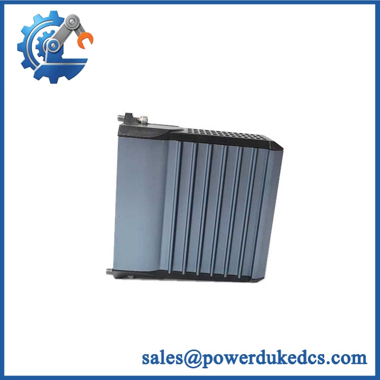
Foxboro E69F-T-I2-JRS
Quality Assurance SOP
The following pre-shipment procedure is designed for the Foxboro E69F-T-I2-JRS current-to-pneumatic converter. Because this is an electromechanical pneumatic instrument rather than a networked processor module, acceptance testing must focus on its electrical input, pneumatic response, mechanical condition, and enclosure configuration.
| QA Stage | Inspection and Test Procedure | Acceptance Criteria |
|---|---|---|
| Part Identification | Verify the model designation, complete suffix, nameplate markings, and available traceability records. Check the ordering code against the requested configuration. | Model and configuration match the purchase specification; discrepancies are documented before shipment. |
| OEM Authenticity Visual Inspection | Inspect labels, housing, threaded cover, junction box, fasteners, connectors, and visible manufacturing marks. Review available documentation for unexplained alterations. | No unresolved identification discrepancies, visible unauthorized modifications, or damaged interfaces. |
| Mechanical Inspection | Examine the enclosure, mounting points, electrical entry, pneumatic ports, filter regulator, and pressure gauges. | No visible cracks, damaged threads, leaking fittings, or other defects that compromise installation. |
| Configuration Verification | Confirm the 4–20 mA or required split-range input, output code 2, direct/reverse action, and J/R/S accessory configuration. | Actual configuration matches the approved application requirements. |
| Electrical Input Test | Apply a controlled DC current using a suitable calibrator. Test representative points across the specified input range while monitoring the resulting pneumatic output. | Output changes consistently with the configured input and action. |
| Pneumatic Output Calibration | Apply the approved instrument-air supply and measure output pressure at the required input points with a calibrated pressure gauge. | Output meets the applicable OEM tolerance and the specified 20–100 kPa or 3–15 psi operating range. |
| Filter Regulator Inspection | Inspect the adjustable regulator and filter assembly. Verify adjustment and pressure stability using the approved test procedure. | Regulated air supply meets the applicable requirements without unexplained pressure fluctuation. |
| Leakage Inspection | Inspect pneumatic connections and accessible fittings using an approved leak-detection method. | No unacceptable leakage or loss of pressure under the specified test conditions. |
| Direct/Reverse Action Verification | Increase and decrease the input signal while observing output pressure. Compare the measured response with the required control-loop action. | Correct response direction and repeatable output throughout the tested range. |
| Startup Diagnostic Check | This model has no standalone processor POST or ERR/RUN diagnostic LEDs. Verify functional response through the controlled electrical input and pneumatic output tests instead. | Converter responds as specified, with no unexplained pressure interruption or mechanical sticking. |
| Communication Handshake Verification | Network communication is not applicable to this analog I/P converter. Verify the electrical input circuit and pneumatic signal path instead. | The input signal is received correctly and the corresponding pneumatic output is produced. |
| Final Inspection and Packing | Record the model, condition, configuration, test equipment, measured results, and unresolved limitations. Protect threaded surfaces, gauges, electrical entries, and pneumatic connections during packing. | Inspection record complete; instrument protected against impact, contamination, and damage during transport. |
Testing limitation: Bench calibration demonstrates the converter’s response under the test conditions; it does not establish suitability for every hazardous-area installation or actuator. Actual certification, supply-air requirements, output tolerance, and installation constraints must be verified against the applicable OEM documentation.
For procurement acceptance, distinguish visual inspection from functional calibration and enclosure-certification verification. State the actual supplied condition and warranty terms, and provide measured input/output test results when testing has been completed.