

Description
- Model: AA1543-S00 S1
- Brand: Yokogawa
- Series: AAI543 Analog Output Module
- Part Type: 16-channel isolated analog output module
- Core Function: Converts FCS control data into isolated 4–20 mA field output signals for valves, actuators, and other final control elements.
- Key Specs: 16 isolated outputs; 4–20 mA DC; 0–750 Ω allowable load; 1500 VAC output-to-system withstand voltage; 10 ms data update period.
- Identification Note: Yokogawa’s official documentation identifies the module family as AAI543 rather than AA1543. The requested AA1543-S00 S1 appears to be a transcription variant of AAI543-S00 S1.
Product Introduction
A single failed output card can remove control of multiple final elements at once. The Yokogawa AAI543-S00 S1 is a 16-channel isolated analog output module for the CENTUM VP FIO architecture, providing 4–20 mA outputs to field devices. Yokogawa’s specifications identify AAI543 as a 16-channel isolated current-output module and allow it to operate in a dual-redundant configuration.
The standard AAI543-S00 configuration uses the -S standard type, 0 basic option, and the S1 hardware style designation used in supplier inventory records. The official Yokogawa specification lists 0–750 Ω allowable load resistance, 1500 VAC output-to-system withstand voltage for one minute, <0.65 mA circuit-open detection, and a 10 ms data update period.For legacy migration work, verify the complete suffix before purchasing because Yokogawa also offers HART, fast-switching, G3, explosion-protection, and different terminal-interface configurations.
Core Technical Specifications
| Parameter | Value |
|---|---|
| Manufacturer | Yokogawa Electric Corporation |
| Documented Model Family | |
| Requested Identifier | AA1543-S00 S1 |
| Product Type | Analog Output Module |
| Output Channels | 16, isolated |
| Output Signal | 4–20 mA DC |
| Allowable Load Resistance | 0–750 Ω |
| Circuit-Open Detection | Less than 0.65 mA |
| Accuracy | ±48 µA |
| Data Update Period | 10 ms |
| Ambient Temperature Drift | ±16 µA / 10 °C |
| Output-to-System Withstand Voltage | 1500 VAC, 1 minute |
| Redundant Operation | Supported |
| Standard Redundant Switchover | Maximum 100 ms below 4 mA for -0 |
| Fast Redundant Switchover | Maximum 2 ms below 4 mA for -1 |
| Maximum Current Consumption | 230 mA at 5 VDC; 540 mA at 24 VDC |
| External Interface Options | KS cable, pressure-clamp terminal block, dual pressure-clamp terminal block, MIL cable |
| KS Interface Adapter | ATK4A-00 when /K4A00 is selected |
| Compatible Systems | Yokogawa CENTUM VP / FIO architecture |
| Typical Weight | Approximately 0.4 kg |
Yokogawa’s official specification confirms the electrical characteristics and ordering structure, including /K4A00 for the ATK4A-00 KS Cable Interface Adapter.
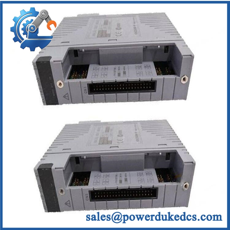
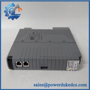
Yokogawa AA1543-S00 S1
Application Scenarios & Pain Points
During a refinery turnaround, an failure can remove several control-valve outputs simultaneously. Sixteen isolated 4–20 mA channels allow one module to service multiple final-control loops from the FCS.
For chemical processing, the isolated output architecture helps separate field output circuits from the DCS system side. The specified 1500 VAC withstand rating is relevant during cabinet design and maintenance testing.
In power-generation plants, redundant modules can be used where continued analog output availability matters. Yokogawa documents standard and fast redundant switchover variants, with -1 intended where a fast response is required.
For an existing CENTUM VP installation, replacing the exact variant can preserve the established I/O engineering, field wiring, and termination system. (This is particularly useful when the shutdown window is measured in hours rather than days.)
At cabinet temperatures approaching 50 °C, the module’s temperature environment should be checked against the specific suffix and installation location. Yokogawa’s broader FIO documentation distinguishes standard and G3 temperature-support options.
🚨 Common Error Codes & Diagnostic Symptoms
Symptom/Code: Output remains below the commanded 4 mA level
→ Diagnosis: Possible failed output channel, poor field termination, excessive load resistance, or open-loop condition. The specification identifies circuit-open detection below 0.65 mA.
→ Action: Verify output current with a calibrated meter and test the loop using a representative load; replace the module if the channel fails controlled output testing.
Symptom/Code: Several output channels fail together
→ Diagnosis: Suspect module power, system-bus communication, common connector faults, or module-level hardware failure before replacing individual field devices.
→ Action: Check module status, supply rails, connector seating, and representative channels; replace the when module-level testing confirms failure.
Symptom/Code: Output flicker during redundant-module switchover
→ Diagnosis: The system may be using a standard-response configuration where the output can fall below 4 mA for up to the documented switchover interval. Yokogawa specifies up to 100 ms for -0 and up to 2 ms for -1.
→ Action: Confirm whether the installed application requires the fast-response -1 configuration.
The is not documented with a universal standalone numeric diagnostic-code system. Troubleshooting normally combines DCS alarms, channel measurements, module status, and loop tests.
🚨 Cross-Reference & Lifecycle Migration
Lifecycle Status: Established CENTUM VP I/O product family; exact S1 variant availability should be confirmed before stocking decisions.
Yokogawa’s official documentation identifies as a 16-channel isolated analog output module. The ordering structure includes several meaningful configuration choices:
- Standard 4–20 mA isolated analog output configuration.
- HART-enabled version.
- 5 / 6: Standard or fast switchover in redundant operation without explosion protection.
- E / F: Corresponding explosion-protection variants.
- 0 / 1 / 3: Basic, G3, or G3 plus extended-temperature options.
- /K4A00: ATK4A-00 KS Cable Interface Adapter.
- /A4S00 / A4S10 / A4D00 / A4D10: Various pressure-clamp and dual-terminal interfaces.
Compatibility Assessment
- -S00 S1 → identical -S00 S1: Direct like-for-like replacement after connector and system verification.
- -S00 S1 → -Hxx: Not identical; HART functionality and configuration differ.
- -0 → -1: Functionally related but different redundant-switchover performance; do not substitute without checking loop requirements.
- Not a substitute; AAV544 is a voltage-output module rather than 4–20 mA current output.
- Firmware flashing: Not normally required for a same-variant replacement; verify the installed CENTUM configuration and applicable module revision.
- Hardware modification: Normally unnecessary when the same terminal/cable interface is retained.
- Buffer-stock strategy: Maintain at least one verified spare for critical output loops, with the exact suffix and interface recorded in the spare-parts register.
Field Engineer’s Tech Notes
First warning: check the interface option, not just . Yokogawa supports KS-cable and several pressure-clamp configurations. /K4A00 specifically identifies the ATK4A-00 KS Cable Interface Adapter. A base with a different external interface can require different termination hardware.
Second warning: confirm the redundant-response requirement. -0 and -1 are not identical in switchover behavior. Yokogawa documents up to 100 ms below 4 mA for the standard response and 2 ms for the fast response. A control-valve loop with a tight process response requirement may need the fast configuration.
Strict QA & Testing SOP
- Inbound inspection: Verify Yokogawa labeling, complete identification, packaging, quantity, and actual-unit condition.
- Nameplate verification: Record model, suffixes, serial number, date code, and visible hardware revision.
- Physical inspection: Check the PCB, connectors, terminal interface, mounting points, labels, and evidence of corrosion, contamination, or unauthorized repair.
- ESD-controlled handling: Use a grounded workbench, wrist strap, and conductive packaging during inspection.
- Power verification: Apply the appropriate system supply under controlled conditions and record module current.
- POST/status check: Confirm module startup, system recognition, and expected status behavior.
- Output-source simulation: Apply controlled output commands through the test system and verify 4–20 mA response.
- All-channel testing: Test every available output channel where practical rather than relying only on one sample channel.
- Load testing: Test outputs with representative loop resistances up to the documented 750 Ω maximum.
- Open-loop test: Introduce an approved controlled open-loop condition and verify circuit-open detection behavior.
- Isolation test: Perform approved withstand or insulation testing using laboratory procedures appropriate for the module; Yokogawa specifies 1500 VAC for one minute between output and system.
- Redundancy test: Where a dual-module test rack is available, verify standard or fast switchover behavior according to the installed variant.
- Output accuracy check: Compare representative currents against calibrated measurement equipment.
- Thermal observation: Run representative load conditions and monitor temperature, output stability, and abnormal component heating.
- Power-cycle test: Verify repeatable initialization following controlled power interruption and restoration.
- Final QC release: Record output measurements, load values, diagnostic behavior, revision information, photographs, and inspector approval.
- Anti-static packaging: Protect the module and external connectors from ESD and mechanical damage.
- Test evidence: Test videos are available for applicable bench testing and functional verification.
Yokogawa’s published data supports the 16-channel architecture, 4–20 mA output, 0–750 Ω load range, circuit-open detection, and redundant-operation specifications.
Buyer’s FAQ
Q1. Can I hot-swap the -S00 S1 while CENTUM VP is operating?
A: Yokogawa’s FIO architecture supports redundant configurations for applicable variants, but do not assume every installation permits unrestricted live removal. Follow the approved CENTUM VP maintenance procedure and confirm that the specific module and node configuration supports online replacement before disconnecting an energized card.
Q2. How do I verify a New Original AA1543-S00 S1 when the nameplate says ?
A: Use the manufacturer’s documented identifier as the controlling product family. Yokogawa’s official documentation identifies as the 16-channel isolated analog output module. The requested AA1543 spelling should be treated as a procurement/search variant unless the physical nameplate shows otherwise.
Q3. Can I replace an -0 wi?
A: Not without engineering review. Yokogawa specifies different redundant switchover performance: up to 100 ms below 4 mA for -0 versus 2 ms.The required response should be determined from the connected final-control loop.
Q4. Does this module require firmware flashing after replacement?
A: A routine firmware flash should not be assumed for an identical hardware variant. Verify the installed CENTUM VP configuration, module suffix, termination method, and redundancy settings before commissioning.
Q5. What warranty should procurement require?
A: Specify the warranty period, DOA coverage, functional-failure coverage, return authorization process, inspection window, and freight responsibility in the quotation. For a critical analog output module, also require the exact identification, hardware revision, condition, and documented channel-test results before shipment.



 Start Chat


