

Description
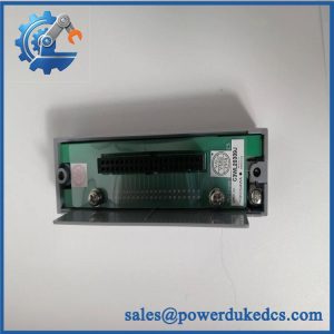
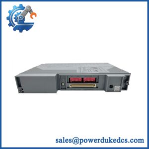
- Model: AAI543-H50 S1
- Brand: Yokogawa
- Series: CENTUM VP / CENTUM CS 3000 FIO
- Part Type: 16-channel isolated analog output module
- Core Function: Generates sixteen independent 4–20 mA output channels for final control elements and supports digital communication through HART on the H-version architecture.
- Key Specs: 16 channels | 4–20 mA DC | isolated outputs | HART-capable | 10 ms data-update period | 750 Ω maximum load resistance. Yokogawa identifies AAI543 as a 16-channel isolated analog output module, while
-Hdenotes the HART-enabled version. - Stock Signal: Current secondary inventory records list AAI543-H50 S1 in new-stock condition; physical quantity and exact revision should be confirmed before PO release.
Product Introduction
Structure A — Pain-Point Hook
A failed analog-output channel can take a control valve, actuator, or VFD reference out of service even when the rest of the FCS continues running. The Yokogawa AAI543-H50 S1 provides 16 isolated 4–20 mA outputs within the CENTUM FIO architecture, while the H-version supports HART digital communication over the analog loop. Yokogawa’s specification identifies AAI543 as a 16-channel isolated AO module and separates standard, redundant-response, and explosion-protection variants through the suffix structure.
For a brownfield DCS, an exact module replacement can avoid unnecessary panel rewiring and a wider legacy migration project. The -H50 version must still be matched correctly: ordering-code differences affect explosion-protection and related configuration options. (Do not purchase on the base AAI543 identifier alone.) Yokogawa also defines /K4A00 as a separate KS Cable Interface Adapter option, so the presence or absence of that option should be checked against the installed FIO arrangement.
Core Technical Specifications
| Parameter | Value |
|---|---|
| Manufacturer | Yokogawa Electric Corporation |
| Model | AAI543-H50 S1 |
| Module Type | Analog Output Module |
| Channels | 16 |
| Output Signal | 4–20 mA DC |
| Isolation | Isolated analog outputs |
| Communication | HART digital communication for the -H version |
| Data Update Period | 10 ms |
| Maximum Load Resistance | 750 Ω |
| Accuracy | ±0.1% of full scale at 25°C, per current secondary technical listings |
| Associated System | CENTUM VP / CENTUM CS 3000 FIO |
| Backplane | Yokogawa ESB |
| Hazardous-Area Variant | -H50 configuration; confirm exact applicable certification from the installed ordering code |
| Operating Temperature | 0°C to +55°C listed by secondary technical sources |
| Approximate Weight | 300 g listed by secondary technical sources |
| Related Interface Option | /K4A00 = ATK4A-00 KS Cable Interface Adapter |
Yokogawa’s primary specification confirms the core architecture, including 16-channel isolated analog output, HART as the -H option, response variants, and the optional /K4A00 interface adapter. Secondary technical records provide the 10 ms update period and 750 Ω load figure.
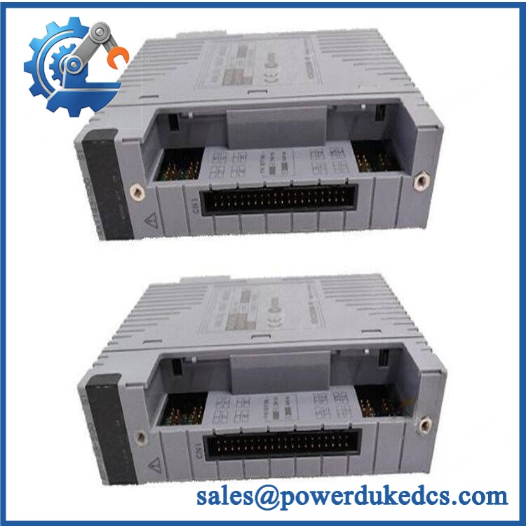
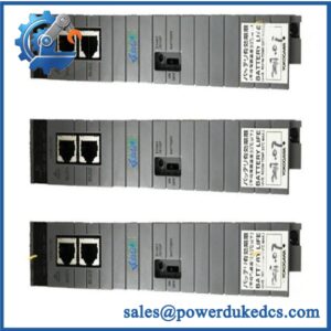
Yokogawa AAI543-H50 S1
Application Scenarios & Pain Points
At a refinery control console, one failed output may leave a control valve frozen at its last commanded condition. An exact -H50 S1 replacement can restore the affected output group without changing the entire FIO assembly.
For LNG and chemical-processing applications, HART communication is useful when the analog loop also carries digital instrument information. The H-version is intended for smart-field-device communication while retaining the standard 4–20 mA control signal.
In power generation, isolated outputs help separate individual control loops electrically. Engineering should still verify the field device’s required load and output polarity before commissioning (particularly for long cable runs).
During a brownfield expansion, the 16-channel density allows multiple final-control loops to remain within the existing FIO architecture. Yokogawa’s published family documentation also shows several redundant-response and protection variants, so the complete suffix matters during procurement.
🚨 Common Error Codes & Diagnostic Symptoms
Symptom/Code: Output remains near 0 mA despite a valid FCS command
→ Diagnosis: Possible output-channel electronics failure, open field circuit, incorrect channel configuration, or load/interface problem.
→ Action: Measure the channel at the module terminals and field device, then replace the -H50 S1 if the module output stage is confirmed defective.
Symptom/Code: Output fluctuates or fails under connected load
→ Diagnosis: Suspect excessive loop resistance, intermittent terminal connections, output-stage degradation, or field-device loading beyond the module’s specified limit.
→ Action: Measure loop resistance and output current under load; replace the module if the fault follows the channel.
Symptom/Code: HART communication unavailable while analog output remains present
→ Diagnosis: Possible HART configuration issue, incompatible field device, wiring problem, or failure in the module’s HART communication path.
→ Action: Verify loop wiring and HART settings before replacing the complete module.
Yokogawa’s accessible public specification does not publish a ted S1 fault-code table. These entries therefore describe practical troubleshooting symptoms rather than proprietary OEM error codes.
🚨 Cross-Reference & Lifecycle Migration
- Lifecycle status: Supported/established product family with lifecycle exposure, rather than a part that should be treated as permanently secure. Yokogawa maintains a dedicated discontinued-products resource, so current lifecycle status should be checked before long-term stocking decisions.
- Model family: is the core 16-channel isolated analog-output family. The
-Hdesignation adds HART communication; the suffix structure also distinguishes redundant-response and explosion-protection configurations. - Direct replacement: Treat the same as the preferred like-for-like replacement.
- Revision check: The
S1designation should be retained in the RFQ. Do not assery revision has identical hardware behavior without engineering confirmation. - Older-system compatibility: Yokogawa documents for CENTUM VP and related FIO architectures. Exact FCS, node-unit, software-release, and interface-option compatibility must be checked against the installed system.
- Firmware flashing: Not automatically required for a like-for-like module replacement; verify installed system software and module revision before commissioning.
- Buffer-stock strategy: For a plant carryingple S1 channels, 1–2 verified spare modules per critical FIO population is a reasonable starting point, with higher coverage where a single-channel failure can trip a production-critical loop.
- Interface-option warning: If the installed module has
/K4A00, procurement must include or separately source the associated ATK4A-00 KS Cable Interface Adapter.
Field Engineer’s Tech Notes
First warning: Do not confuse with a generic . Yokogawa’s ordering structure assigns meaning to the suffixes for HART, redundancy response, explosion protection, G3, temperature options, and interface accessories. Match the entire ordering designation against the installed card.
Second warning: Check the field loop before condemning the module. A 4–20 mA output that collapses under load may indicate excessive loop resistance or a wiring fault rather than failed electronics. The published maximum load figure should be included in the engineering check, and the actual field-device requirement must be considered.
Strict QA & Testing SOP
- Inbound identity check: Record Yokogawa, , serial number, revision, manufacturing label, and all suffix/options.
- OEM visual inspection: Compare PCB markings, connectors, terminals, labels, component placement, and enclosure condition with a known-good reference.
- Anti-counterfeit screening: Examine marking quality, solder workmanship, connector construction, and signs of unauthorized board repair.
- Mechanical inspection: Check the card edge, retaining hardware, connectors, terminal interface, and housing for damage or contamination.
- Power integrity check: Verify the module’s supply path and grounding before live testing.
- Power-on self-test (POST): Install the module in a compatible Yokogawa FIO test environment and record startup status and diagnostics.
- FCS recognition test: Confirm the correct module identity is recognized by the associated control system without hardware faults.
- 4–20 mA output simulation: Command representative output points and measure actual current using calibrated instrumentation.
- Multi-channel test: Exercise representative channels across the module, including adjacent outputs, to detect intermittent or channel-specific faults.
- Load test: Apply a controlled representative load and verify stable current regulation within the applicable output limits.
- HART communication test: For the H-version, connect a compatible HART field device or simulator and verify digital communication while maintaining the analog output.
- Isolation verification: Check channel-to-channel and channel-to-bus isolation using the approved Yokogawa test procedure.
- Extended run: Operate under representative load for an extended period and monitor output stability and module temperature.
- Final QC release: Record measured current values, load conditions, HART test results, diagnostics, serial traceability, and photographs.
- ESD packaging: Protect the module in antistatic packaging with connector protection and impact-resistant cushioning.
- Test evidence: Test videos are available for qualified units when requested as part of the pre-shipment QC package.
Yokogawa identifies as an FIO analog-output module with 16 isolated channels and defined ordering options, making the complete option code part of the QA acceptance record.
Buyer’s FAQ
Q1. Can I hotthe S1?
Do not assume hot-swapping is acceptable merely because the module is an FIO component. Follow the Yokogawa maintenance procedure and the site’s approved isolation rules before removing or inserting the module. Redundant FIO arrangements may permit specific maintenance strategies, but that decision belongs to the installed system design.
Q2. How do I verify that a “New al” S1 is authentic?
Request photographs of the actual module, including theete S1 marking, serial label, PCB identification, connectors, and option codes. Current secondary listings advertise new units, but listing status alone does not establish authenticity or physical stock.
oes S1 need firmware flashing before installation?
Not normally for an exact like-for-like replacement. The engineering team should still verify the installed CENTUM VP/CS 3000 environment, module revision, FIO configuration, and applicable software requirements before commissioning.
Q4. What is the differenceen S1 and a standard ?
is the 16-channel isolated analog-output family. The -H suffix identifies HART-capable digital communication, while the rest of Yokogawa’s ordering code distinguishes response behavior, protection, environmental options, and interface accessories.
Q5. What warranty should procurement require?
Specify exactly, including revision and any interface option. Require a written warranty, DOA protection, output-current test record, HART verification where applicable, serial traceability, and a defined return period. For critical DCS spares, actual-unit photographs should form part of the purchase acceptance package.



 Start Chat


