

Description
- Model: AAT141-S00 S2
- Brand: Yokogawa
- Series: AAT141 FIO Analog I/O Module
- Part Type: 16-channel isolated thermocouple/mV input module
- Core Function: Acquires thermocouple and low-level millivolt signals and transfers the measured temperature/process data into the Yokogawa FCS.
- Key Specs: 16 isolated inputs; TC types J, K, E, B, R, S, T, N; mV ranges of -100 to 150 mV and -20 to 80 mV
- Data Update Period: 1 second
- Accuracy: ±30 µV for thermocouple / -20 to 80 mV; ±80 µV for -100 to 150 mV
- Reference Junction Compensation: Within ±1°C under specified conditions
- Redundancy: Dual-redundant operation supported
- Input Protection: ±5 V allowable input voltage
- Condition: New Original / New Surplus / Tested Refurbished — verify exact physical configuration before PO
Yokogawa identifies AAT141 as a 16-channel isolated TC/mV input module for FIO, supporting J, K, E, B, R, S, T, and N thermocouple types plus two millivolt ranges.
Product Introduction
Sixteen isolated temperature inputs make AAT141-S00 S2 a high-density replacement for distributed thermocouple measurement in a Yokogawa FIO node. Each channel can be individually configured for thermocouple or millivolt input, while the module supports dual-redundant operation. The documented update period is 1 second, and the input circuitry provides 1500 VAC isolation between the field input and system side under the specified test condition.
For field maintenance, the important checks are the thermocouple type, wiring arrangement, module revision, and terminal-board configuration. Yokogawa specifically requires a non-grounded thermocouple for AAT141 because this is an isolated module; grounding multiple thermocouples can create multi-point ground paths and temperature errors. The S00 designation should therefore be matched against the complete installed configuration before a legacy migration or spare-card replacement is approved.
Core Technical Specifications
| Parameter | Value |
|---|---|
| Model | AAT141-S00 S2 |
| Manufacturer | Yokogawa Electric Corporation |
| Product Type | Isolated TC/mV Input Module |
| Input Channels | 16, isolated |
| Thermocouple Types | J, K, E, B, R, S, T, N |
| mV Input Range | -100 to 150 mV |
| Additional mV Range | -20 to 80 mV |
| Channel Selection | TC/mV individually selectable per channel |
| Allowable Input Voltage | ±5 V |
| Input Resistance | 2 MΩ or higher |
| Withstanding Voltage | 1500 VAC for 1 minute, input-to-system |
| TC Accuracy | ±30 µV |
| mV Accuracy | ±80 µV for -100 to 150 mV; ±30 µV for -20 to 80 mV |
| Reference Junction Compensation | Within ±1°C under specified conditions |
| Signal Source + Wiring Resistance | 1000 Ω maximum for TC/mV input |
| Data Update Period | 1 second |
| Burnout Detection | Selectable; 60-second detection time |
| Temperature Drift | ±80 µV/10°C or ±30 µV/10°C depending on input range |
| Maximum Consumption | 450 mA at 5 VDC |
| Weight | Approx. 0.2 kg |
| External Connection | Pressure clamp terminal |
| Redundancy | Dual-redundant configuration supported |
These values are taken from Yokogawa’s published FIO specification. The manufacturer also notes that Type B does not perform temperature compensation and cannot measure below 44°C.
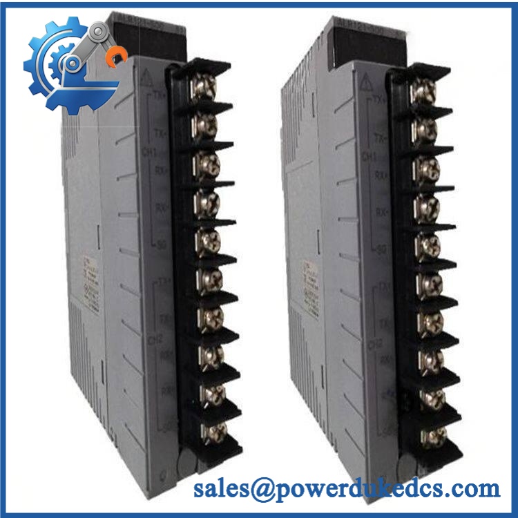
Yokogawa AAT141-S00 S2
Application Scenarios & Pain Points
When a temperature-input module fails, the symptom often appears first as bad process data rather than a completely dead cabinet. -S00 S2 is designed for applications where multiple thermocouple or low-level millivolt signals must reach a Yokogawa FIO node through isolated channels.
- Refineries: Reactor, furnace, heater, and process-line temperature points can be concentrated on sixteen isolated channels. For cabinets exposed to 50°C+ ambient conditions, verify the complete node thermal environment because reference-junction accuracy changes with terminal temperature.
- Chemical processing: Multiple K-, J-, or T-type thermocouples can be assigned individually by channel, allowing mixed measurement points on one module.
- Power generation: Turbine auxiliaries, boiler equipment, bearings, and casing temperature measurements can use the isolated TC interface without replacing the complete FIO architecture.
- Gas processing: High-density temperature measurement can reduce the number of separate I/O interfaces required in a distributed cabinet.
- Process utilities: Low-level millivolt sensors can use the module’s -20 to 80 mV or -100 to 150 mV ranges, provided the signal source and wiring resistance remain within specification.
🚨 Common Error Codes & Diagnostic Symptoms
Symptom/Code: Temperature reading suddenly shifts after replacing the card
→ Diagnosis: Incorrect thermocouple type, reversed polarity, unequal lead resistance, incorrect channel TC/mV setting, or an unwanted ground path can produce an apparent calibration error.
→ Action: Verify the channel setting, sensor type, polarity, and wiring before replacing another module.
Symptom/Code: Multiple temperature channels show unexplained offsets
→ Diagnosis: A multi-point ground condition is a prime suspect when grounded thermocouples are connected to this isolated module. Yokogawa specifically warns that ground-type thermocouples can create multiple grounds and temperature errors.
→ Action: Correct the field-sensor grounding arrangement; replace the module only after the external wiring is proven correct.
Symptom/Code: Channel indicates burnout / abnormal input
→ Diagnosis: Open thermocouple wiring, excessive source resistance, defective sensor, or an input-channel fault can trigger the burnout indication. ‘s burnout detection can be enabled for all channels with a documented 60-second detection time.
→ Action: Check sensor continuity and wiring first; replace the module when the fault follows the card.
🚨 Cross-Reference & Lifecycle Migration
- Lifecycle Status: Legacy FIO hardware; verify current commercial availability by exact suffix and style. Yokogawa continues to publish technical documentation, but a current manual listing alone should not be interpreted as unrestricted factory availability.
- Base Model: — 16-channel isolated TC/mV input module.
- Style: S2 — treat the style revision as part of the procurement specification rather than an interchangeable cosmetic suffix.
- Input Technology: TC and mV; each channel can be configured individually.
- Redundancy: Two matching modules can be used in a dual-redundant configuration.
- Terminal Interface: Pressure-clamp terminal arrangement; the associated terminal board/cable must match the FIO architecture. Yokogawa lists ATT4S as the 16-point pressure-clamp terminal board associated with .
- Firmware Flash: No blanket firmware-flashing requirement is established for a like-for-like replacement. The installed CENTUM/FIO node configuration and hardware style should still be checked.
- Cross-Reference: Do not substitute AAR181, which is an RTD input module; is specifically the TC/mV device.
- Buffer Stock Strategy: For critical temperature loops, maintain at least one tested spare and retain documented channel-type settings.
One engineering detail deserves emphasis: is not a universal temperature-input card. Its field sensor technology is TC/mV, and Yokogawa explicitly requires non-grounded thermocouples for this isolated design.
Field Engineer’s Tech Notes
Warning 1 — Photograph the channel configuration before pulling the module.
Every channel can be set individually for TC or mV input. A replacement card with the wrong setting can produce a perfectly believable but incorrect temperature value. Do not troubleshoot the transmitter first until the channel configuration has been checked.
Warning 2 — Do not use grounded thermocouples across multiple channels.
This is one of the more important field traps with . Yokogawa states that the isolated input architecture requires non-grounded thermocouples; multiple grounded sensors can create multi-point grounding and introduce temperature errors.
Also verify that the resistance of the signal source plus wiring stays within the specified limit. A long or poorly selected thermocouple extension can create a measurement problem that looks like a bad input card.
Strict QA & Testing SOP
Step 1 — Inbound Inspection
- Confirm Yokogawa AAT141-S00 S2 against the physical label.
- Record serial number, style, date information, and hardware revision.
- Perform OEM marking and anti-counterfeit visual inspection.
- Photograph the nameplate, connector, and PCB.
Step 2 — Mechanical Inspection
- Check the module housing for impact, corrosion, contamination, or unauthorized repair.
- Inspect connector pins and terminal interfaces.
- Verify mechanical fit within the intended FIO node.
Step 3 — Electrical Safety Checks
- Verify isolation integrity using an approved laboratory procedure.
- Check input-to-system insulation.
- Confirm the test fixture uses the specified supply conditions.
- Do not apply arbitrary voltage to TC/mV inputs.
Step 4 — Live Rig Testing
- Install the in a compatible Yokogawa FIO test node.
- Perform power-up diagnostics.
- Confirm module recognition.
- Exercise representative channels with calibrated thermocouple simulators or millivolt sources.
Step 5 — Temperature Input Accuracy Test
- Test representative channels at low, mid-scale, and high points.
- Verify Type K, J, or another required TC type against a calibrated source.
- Check the documented ±30 µV TC accuracy under the applicable conditions.
- Test the appropriate mV range where required.
Step 6 — Reference Junction Test
- Verify reference-junction compensation using a controlled terminal environment.
- Record terminal temperature and measured error.
- Keep the terminal block environment within the relevant specification during acceptance testing. Yokogawa documents different compensation accuracy across temperature ranges.
Step 7 — Burnout Test
- Simulate an open thermocouple circuit.
- Verify the configured burnout indication.
- Confirm the expected detection behavior over the specified 60-second detection period.
Step 8 — Redundancy Test
- Where the application uses dual redundancy, install a matching module pair.
- Verify normal data acquisition.
- Simulate loss of one module.
- Confirm the remaining path maintains the required measurement function.
- Restore the redundant channel and verify recovery.
Step 9 — Extended Stability
- Operate representative channels continuously.
- Monitor temperature readings, module status, supply behavior, and diagnostic stability.
- Repeat selected measurements after thermal stabilization.
Step 10 — Final QC
- Record serial number and hardware style.
- Document TC types tested and measured errors.
- Issue a serial-number-specific QC/Test Report.
- Apply a QC Passed label.
- Protect the module and connector in anti-static packaging.
Test evidence: Test videos, configuration photographs, and the serial-number-specific QC report should be available for procurement review before shipment.
Buyer’s FAQ
Q1. Can I hot-swap the -S00 S2?
Do not assume that module redundancy makes every live replacement procedure safe. The FIO architecture supports dual-redundant operation, but the acceptable maintenance method depends on the specific node, terminal arrangement, process condition, and site procedure. Verify the redundancy state before removal.
Q2. What exactly must match when buying a “New al” S2?
Match the model, S00 configuration, S2 style, terminal/interface arrangement, and installed FIO architecture. Ask for clear nameplate photographs and serial information before shipment. The sensor technology must also remain TC/mV, not RTD.
Q3. My plant uses Type K thermocouples. Is the module compatible?
Yes. Type K is explicitly supported, along with J, E, B, R, S, T, and N. Each channel can be configured individually for TC or mV input.
Q4. Does replacing the module require firmware flashing?
No blanket module-specific firmware flash is established for a like-for-like replacement. The critical checks are hardware style, FIO node configuration, channel settings, terminal interface, and system compatibility.
Q5. What should warranty and return terms include?
The quotation should identify the exact , serial number, physical condition, warranty period, return procedure, and pre-shipment test scope. For temperature-input hardware, request test evidence covering representative TC/mV channels, burnout response, isolation checks, and the actual serial number shipped.



 Start Chat


