

Description
- Model: ADV551-P00 S2
- Brand: Yokogawa
- Series: CENTUM VP / FIO Digital I/O
- Part Type: 32-channel isolated digital output module
- Core Function: Provides 32 transistor-contact outputs for switching external 24 VDC loads, with selectable status, pulse-width, and time-proportioning output functions.
- Key Specs: 32 outputs | 24 VDC rated voltage | 50 mA rated load per channel | Current-sink output | 20.4–26.4 VDC external supply range | 3 ms or less status-output response. Yokogawa confirms these core specifications for ADV551.
- Style / Revision: P00 / Style S2 as identified on current inventory records; the P00 suffix corresponds to the basic ADV551 configuration, while the published Yokogawa documentation defines the underlying ADV551 electrical architecture.
- Stock Signal: Current independent inventory listings report new units available; actual quantity and the exact S2 marking should be confirmed before PO release.
Product Introduction
Structure B — Technical Direct
Installed in the Yokogawa FIO architecture, the ADV551 is a 32-channel, 24 VDC isolated digital output module used in ESB Bus Node Units and Field Control Units. Yokogawa specifies a current-sink output format, a 20.4–26.4 VDC external field-supply range, and support for ordinary status output, one-shot pulse-width output, and time-proportioning ON/OFF output.
The P00 configuration is the basic type, and the S2 style is widely identified on market inventory records for this module. In field deployments, retaining an exact spare avoids unnecessary changes to the existing FIO cabinet, field terminals, and control logic. That is particularly useful for legacy migration programs where the surrounding Yokogawa infrastructure remains serviceable (verify the complete nameplate and installed node type before approving a replacement).
Core Technical Specifications
| Parameter | Value |
|---|---|
| Manufacturer | Yokogawa Electric Corporation |
| Model | ADV551-P00 S2 |
| Base Model | |
| Series | CENTUM VP / FIO Digital I/O |
| Module Type | Digital Output Module |
| Number of Output Channels | 32 |
| Rated Applied Voltage | 24 VDC |
| Load Voltage | 24 VDC, 50 mA |
| External Power Supply Range | 20.4–26.4 VDC |
| Output Format | Current sink |
| Maximum Load Current | 100 mA/channel at 26.4 V |
| Maximum Output ON Voltage | 2 VDC |
| Maximum OFF-State Leakage | 0.1 mA |
| Withstanding Voltage | 2 kVAC for 1 minute between output signal and system; 500 VAC for 1 minute between commons |
| Status Output | ON/OFF status output |
| Pulse Width Output | One-shot pulse width |
| Time-Proportioning Output | ON/OFF |
| Status Output Response | 3 ms or less |
| Mixed Status/Pulse Output Response | 10 ms or less |
| Pulse Width Range | 8 ms to 7200 s |
| Pulse Width Resolution | 8 ms, with maximum 1 ms additional ON/OFF delay |
| Maximum Internal Consumption | 700 mA at 5 VDC |
| Maximum External Supply Consumption | 60 mA |
| Approximate Module Weight | 0.20 kg |
| External Connection | Pressure-clamp terminal, AKB331 dedicated cable, or MIL connector cable |
| Dual Redundancy | Supported for |
| P00 Configuration | Basic type |
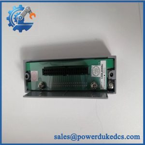
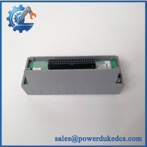
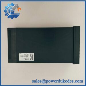
All core electrical values above come from Yokogawa’s published specification. Current inventory records identify the specific ADV551-P00-S2 configuration and report approximately 220–230 g and roughly 10.7 × 13.0 × 3.3 cm. Those physical figures should be treated as inventory references rather than certified dimensional tolerances.
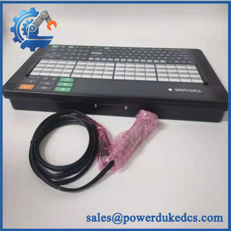
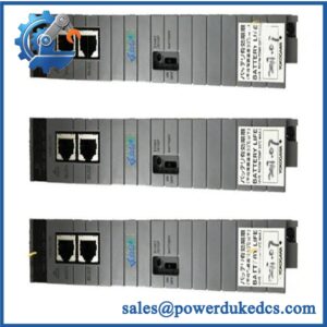
Yokogawa ADV551-P00 S2
Application Scenarios & Pain Points
A refinery operator sees several discrete commands disappear from the field while the FCS remains online. Because the contains 32 outputs, a connector or common-side problem can affect several channels at once. Replacing the output module can restore the existing control architecture without moving the cabinet’s field wiring.
For boiler and utility systems, the pulse-width and time-proportioning functions can be useful for controlled ON/OFF devices. Yokogawa specifies an output pulse-width range of 8 ms to 7200 s, giving the module considerably more flexibility than a simple status-output card.
In chemical processing, current-sink behavior deserves attention. The field circuit must be wired so the external 24 VDC supply and load are arranged correctly; reversing the expected sourcing/sinking architecture can leave a healthy output appearing dead.
Within a power-generation FIO node, dual redundancy can be used with modules. Yokogawa explicitly states that and ADV561 can operate in dual-redundant configurations.
During brownfield maintenance, the 24 VDC field supply range of 20.4–26.4 VDC should be measured at the installation rather than assumed from the nominal 24 V value. Voltage drop across long wiring can create apparent output faults.
🚨 Common Error Codes & Diagnostic Symptoms
Symptom/Code: Multiple output channels remain OFF despite valid FCS commands
→ Diagnosis: Check the external 24 VDC field supply, common wiring, connector path, and output-module status before replacing individual field devices. uses a current-sink output architecture.
→ Action: Verify the field supply and output terminals; replace the when the module-side output fault is confirmed.
Symptom/Code: Output ON voltage rises above the expected level
→ Diagnosis: A degraded transistor output stage, excessive load, or poor field return path can produce abnormal ON-state voltage. Yokogawa specifies a maximum output ON voltage of 2 VDC.
→ Action: Measure the output under the actual load and replace the module if the channel fails the approved electrical test.
Symptom/Code: Intermittent switching or missed pulse outputs
→ Diagnosis: Inspect field-supply stability, connector condition, channel loading, and output configuration. Pulse-width and time-proportioning modes also have defined timing constraints.
→ Action: Validate the configuration and wiring; replace the if the fault remains localized to the module.
Yokogawa’s accessible public specification does not publish an -specific numeric diagnostic-code table. These entries are practical hardware symptoms rather than OEM fault-code assignments.
🚨 Cross-Reference & Lifecycle Migration
- Lifecycle status: Legacy / lifecycle-risk spare. Yokogawa maintains a dedicated discontinued-products resource, while current secondary inventories continue to list -P00-S2. For a plant with substantial installed population, maintaining verified spare coverage is sensible.
- Base model: = 32-channel, 24 VDC isolated digital output module.
- P00 meaning: Yokogawa’s suffix table identifies 0 as the basic type for ; the complete ordering code must still be checked against the installed module.
- S2 identification: Current inventory sources identify the requested unit as ADV551-P00 S2.
- Related model: ADV561 provides 64 digital output channels and uses a different output capacity and power-consumption profile; it is not an automatic drop-in substitute for .
- Interface options: Yokogawa lists ATD5A-00-family pressure-clamp terminal arrangements and AKB331 dedicated cabling for configurations. Confirm the installed interface before ordering.
- Firmware flashing: Not normally required for a like-for-like replacement. The module’s configuration and the host CENTUM/FIO environment still require engineering verification.
- Dual redundancy: Supported by the family, but the installed node and system configuration determine whether redundant operation is actually implemented.
- Buffer-stock strategy: For critical discrete-output nodes, 1–2 verified spares per critical FIO population is a practical starting point, with higher coverage where a failed 32-channel card can affect shutdown or production-critical commands.
Field Engineer’s Tech Notes
First warning: Do not assume every 24 VDC output is wired the same way. The is a current-sink module. Check the external field-supply path, load return, common grouping, and terminal assignment against the Yokogawa drawing before energizing a replacement.
Second warning: Take a close look at the terminal and cable option before removing the old card. Yokogawa supports pressure-clamp terminals, dedicated AKB331 cable, and MIL connector cable arrangements. The wrong interface accessory can turn a simple module swap into an unplanned wiring job.
Strict QA & Testing SOP
- Inbound identity check: Record Yokogawa, ADV551-P00 S2, serial number, revision, manufacturing label, and all suffix markings.
- OEM visual inspection: Compare PCB layout, component placement, connectors, labels, terminal interface, and board finish with a known-good reference.
- Anti-counterfeit screening: Inspect markings, solder workmanship, connector construction, component identity, and evidence of unauthorized repair.
- Mechanical inspection: Check the card edge, mounting hardware, terminal interfaces, and connector housings.
- Power-path verification: Confirm the test setup provides the correct internal and external supply arrangement before energization.
- Power-on self-test: Install the module in an approved Yokogawa FIO test environment and record startup status and diagnostic behavior.
- Module recognition test: Confirm the host system identifies the correctly.
- 24 VDC output test: Exercise representative channels using a controlled external field supply and verify output switching.
- Current-sink verification: Confirm the output stage switches the intended load path correctly under representative conditions.
- Voltage-drop check: Measure ON-state voltage against the applicable limit; Yokogawa specifies 2 VDC maximum.
- Leakage test: Measure OFF-state leakage and verify it remains within the specified 0.1 mA maximum.
- Pulse test: Where the P configuration is applicable, exercise representative pulse-width and time-proportioning functions and verify timing.
- Response-time check: Verify representative status-output response and confirm behavior against the specified 3 ms or less value.
- Load test: Operate selected channels under controlled load and monitor current, voltage drop, module temperature, and intermittent behavior.
- Redundancy test: Where the customer’s architecture uses dual-redundant modules, verify primary/standby recognition and appropriate transfer behavior.
- Extended run: Maintain representative outputs for a controlled test interval and record any channel dropouts.
- Final QC release: Record measured values, test configuration, serial traceability, photographs, and technician sign-off.
- ESD packaging: Place the module in antistatic packaging with connector protection and shock-resistant cushioning.
- Test evidence: Test videos are available for qualified units when requested as part of the pre-shipment QC package.
Yokogawa’s published specification also states that a spark-killer diode should be connected when the is used to drive a DC relay. That detail belongs in the final wiring review for relay-driven loads.
Buyer’s FAQ
Q1. Can I hotthe S2?
Do not assume hot-swapping is permitted. The safe replacement method depends on the specific FIO node, redundancy arrangement, field load, and plant procedure. Isolate the affected circuit according to the approved Yokogawa maintenance procedure before removal.
Q2. How can I verify a Newnal S2?
Ask for photographs of the actual module, including the complete marking, serial label, PCB identification, connectors, and terminal/interface arrangement. Current market listings identify new units, but physical-stock confirmation and nameplate matching remain necessary.
Q3. Does this module need firmware flashing?
For a like-for-like replacement, firmware flashing is not normally the first concern. Verify the CENTUM/FIO configuration, module recognition, output assignments, and any applicable system revision before commissioning.
Q4. Can ADV561 replace because both are digital outputs?
No automatic substitution should be made. is a 32-channel module with a 50 mA load-voltage specification, while ADV561 is a 64-channel module with different channel capacity and external-supply requirements. The two models serve different hardware configurations.
Q5. What warranty should procurement require?
Specify exactly, including the P00 and S2 identification. Require a written warranty, DOA protection, documented output-channel testing, serial traceability, actual-unit photographs, and a defined return period. For critical DCS inventory, the acceptance package should also include the pre-shipment QC record.



 Start Chat


