

Description
- Model: PW484-50 S1
- Brand: Yokogawa
- Series: PW484 Power Supply Module Series
- Part Type: 24 VDC Input Power Supply Module
- Core Function: Supplies the internal power rails required by compatible Yokogawa Field Control Units, FIO Node Units, and Optical ESB Bus Repeater Units.
- Key Specs: 24 VDC input ±10%; 5.5 A maximum power consumption; approximately 1 kg; exclusive connector; S1 style.
- Installation: P1/P2 power-supply slots; two identical modules can provide dual redundancy.
Product Introduction
Technical Direct
The PW484 occupies the power-supply position in Yokogawa FCU, FIO Node Unit, and Optical ESB Bus Repeater architectures. Unlike the PW481 and PW482, which accept AC input, PW484 is the 24 VDC input version. Yokogawa specifies an input range of 24 VDC ±10%, maximum power consumption of 5.5 A, an exclusive connector, and approximately 1 kg unit weight.
The S1 designation is important for replacement procurement. Yokogawa’s product documentation shows an S1-style PW484 nameplate with 24 VDC, 5.5 A supply identification. The module is intended for dedicated Yokogawa system hardware rather than use as a general-purpose 24 VDC power supply (the manufacturer explicitly states that PW48x modules are exclusive to specified FCU, FIO, and optical ESB repeater units).
Core Technical Specifications
| Parameter | Value |
|---|---|
| Manufacturer | Yokogawa Electric Corporation |
| Model | PW484-50 S1 |
| Series | |
| Product Type | 24 VDC Input Power Supply Module |
| Input Voltage | 24 VDC ±10% |
| Maximum Power Consumption | 5.5 A |
| Input Frequency | Not applicable — DC input |
| Input/Output Interface | Exclusive connector |
| Approximate Weight | 1 kg |
| Installation Position | P1/P2 power-supply slots |
| Redundancy | Dual-redundant configuration supported |
| Redundant Pairing | Two identical modules with the same model code |
| Application Hardware | FCU, FIO Node Unit, Optical ESB Bus Repeater Unit |
| Style | S1 |
| Temperature Option | -5 configuration corresponds to standard type without explosion protection; the 1 suffix denotes the ISA Standard G3 temperature option in Yokogawa’s ordering scheme |
| Firmware | Not applicable as a standalone programmable module |
Yokogawa cautions that the output voltage and current are not specified for use as generic supply ratings because is a dedicated system power module.
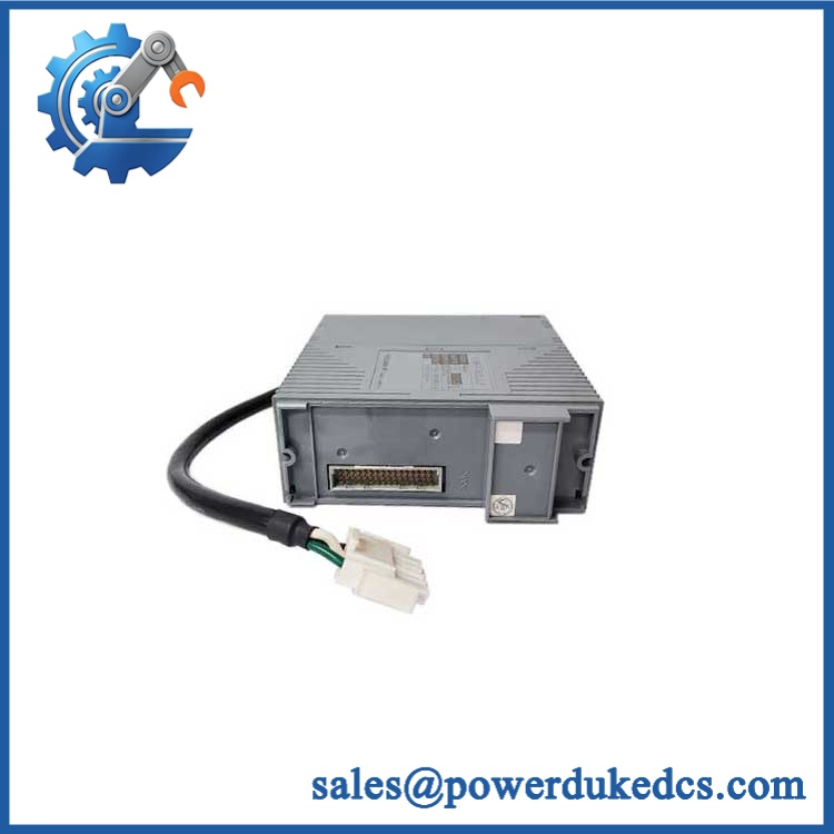
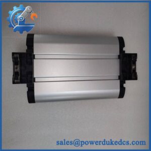
Yokogawa PW484-50 S1
Application Scenarios & Pain Points
A DCS cabinet recovery case: one failed power module can place an FCU or FIO node at risk of losing its required system power path. Replacing the with the correct configuration can restore the existing cabinet without changing the processor or I/O architecture.
In refinery and petrochemical installations, centralized DC systems are common in control cabinets. accepts 24 VDC ±10%, making it appropriate for compatible Yokogawa hardware supplied from a 24 VDC plant distribution system.
For power-generation control networks, dual-redundant installation can reduce exposure to a single power-module failure. Yokogawa specifies that redundancy is achieved by installing two identical modules with the same model code in the designated power positions.
During legacy migration, the main procurement issue is often not firmware. It is selecting the exact configuration and ensuring the receiving FCU or FIO node accepts that hardware revision and connector arrangement.
At ambient temperatures around 60°C, temperature qualification becomes a procurement consideration. Yokogawa distinguishes its standard and ISA G3 temperature options in the suffix structure, so the complete ordering code should be checked against the cabinet design.
🚨 Common Error Codes & Diagnostic Symptoms
Symptom/Code: FCU or FIO node loses power after one PSU fails
→ Diagnosis: power-module failure, DC input interruption, connector fault, or an internal protection event may have removed the required internal supply.
→ Action: Verify the 24 VDC input, connector seating, and module status; replace the when the module fails the controlled power test.
Symptom/Code: Redundant pair does not transfer as expected
→ Diagnosis: The two installed modules may not have matching model/configuration codes, or one module may have an internal fault.
→ Action: Confirm both modules are the approved identical configuration and test each module independently.
Symptom/Code: Node remains unstable despite correct 24 VDC cabinet input
→ Diagnosis: External 24 VDC may be present while the ‘s internal conversion or protection circuitry is defective.
→ Action: Measure the module under an approved Yokogawa test setup and replace the module if its operating characteristics are outside specification.
🚨 Cross-Reference & Lifecycle Migration
Lifecycle Status: Active / Current Documentation Supported. Yokogawa continues to publish current PW481/PW482/ specifications and installation guidance, so should not be classified as obsolete merely because it is used in an older DCS installation.
Critical configuration distinction: identifies the 24 VDC input power-supply family. It must not be confused with:
- PW481: 100–120 VAC input
- PW482: 220–240 VAC input
- 24 VDC input
S1 identification: Yokogawa’s published nameplate example explicitly shows , SUFFIX -S1, STYLE S1, SUPPLY 24VDC – 5.5A. Match this information against the unit being replaced.
Previous revision / replacement relationship: No universal older-part-number cross-reference was established in the manufacturer documentation reviewed. Do not claim that every earlier revision is automatically interchangeable with -50 S1.
Firmware flashing: Not applicable to the power module itself. Compatibility is principally determined by input voltage, mechanical installation, connector arrangement, system hardware compatibility, and redundancy configuration.
Buffer-stock strategy: For a production-critical FCU or FIO node, maintaining one tested spare per installed configuration is reasonable. Where dual-redundant operation is used, spare-stock planning should also consider the risk of both modules sharing the same age and environmental exposure.
Field Engineer’s Tech Notes — Anti-Pitfall Guide
First warning: never use as a generic 24 VDC supply. Yokogawa specifically states that PW48x modules are dedicated to FCUs, FIO Node Units, and Optical ESB Bus Repeater Units. The correct output characteristics are system-specific; verify the receiving Yokogawa hardware before applying power.
Second warning: do not mix configurations in a redundant pair. Yokogawa specifies that dual redundancy uses two identical modules with the same model code. A pair that merely looks identical is not enough. Check the full identification and system ordering record before installing the second module.
Strict QA & Testing SOP
Step 1 — Inbound Verification
Record the complete PW484-50 S1 marking, serial number, style, manufacturer identification, and visible date/lot information.
Step 2 — OEM Visual Inspection
Inspect the nameplate, enclosure, connector, mounting hardware, ventilation areas, labels, and internal construction where accessible. Compare the unit against verified Yokogawa characteristics.
Step 3 — Mechanical Check
Confirm dimensions, module guides, mounting interface, connector alignment, and retention hardware. Look for deformation, corrosion, contamination, or evidence of unauthorized repair.
Step 4 — Electrical Pre-Test
Check connector condition, grounding continuity where applicable, and unintended shorts. Confirm that the test fixture matches the dedicated Yokogawa module interface.
Step 5 — Controlled Power-Up
Apply 24 VDC within the specified ±10% range using a current-limited laboratory supply. Monitor startup current and module behavior.
Step 6 — Input Current Test
Measure operating current under representative system load. The published maximum power-consumption specification is 5.5 A. Record input voltage and current during the test.
Step 7 — System Rack Test
Install the module in a compatible FCU, FIO Node Unit, or Optical ESB Bus Repeater test assembly. Confirm stable system operation and correct module recognition.
Step 8 — Redundancy Test
Where a redundant test setup is available, install two approved identical modules and verify the expected redundant behavior by controlled removal or isolation of one module.
Step 9 — Thermal Observation
Operate under representative load while monitoring module temperature and signs of abnormal heating. For G3-rated configurations, verify that the physical identification matches the required environmental option.
Step 10 — Power-Cycle Test
Perform controlled shutdown/startup cycles and verify repeatable module initialization without abnormal current spikes or system power faults.
Step 11 — Extended Run Test
Operate the module under representative load for an extended interval. Monitor input stability, thermal behavior, intermittent faults, and redundant-system behavior.
Step 12 — Final QC Record
Document part number, style, serial number, input voltage, measured current, rack-test results, redundancy results, thermal observations, and acceptance status.
Packaging: Use ESD-safe packaging, connector protection, moisture control, and impact-resistant outer packaging. Test videos are available for procurement and engineering review.
Buyer’s FAQ — Dynamic Q&A
Q1. Can -50 S1 be hot-swapped?
Do not assume that because the module is installed in a redundant pair it is automatically safe to remove under power. Follow the Yokogawa maintenance procedure for the specific FCU/FIO/ESB configuration and verify that the remaining power path is healthy before any intervention.
Q2. Is -50 S1 the same as PW481 or PW482?
No. All three belong to the PW48x family, but their input sources differ. PW481 is 100–120 VAC, PW482 is 220–240 VAC, and is 24 VDC. Using the wrong family can cause immediate hardware damage.
Q a S1 advertised as “new original” necessarily the correct replacement?
Not solely because it is labeled . Verify the complete suffix/style, nameplate, connector arrangement, and receiving system. Yokogawa’s own S1 nameplate example identifies 24VDC – 5.5A, so those details should match the procurement requirement.
Qes S1 require firmware flashing?
No firmware flashing is normally associated with the power module itself. The engineering checks concern hardware compatibility, input supply, connector/interface, system position, and redundant configuration.
Q5. What warranty should procurement require?
Require a written functional warranty covering controlled power-up, stable operation under representative load, correct rack operation, and—where applicable—redundant operation. The PO should also define the RMA process and exclusions for incorrect input voltage, incompatible equipment, connector damage, or improper installation.



 Start Chat


