

Description
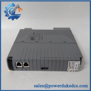
- Model: EC401-10 S2
- Brand: Yokogawa
- Series: CENTUM VP FIO / ESB Bus
- Part Type: ESB Bus Coupler Module
- Core Function: Links a Yokogawa Field Control Unit (FCU) with ESB Bus Node Units so FIO data can travel between the controller and I/O node architecture.
- Key Specs: 128 Mbps I/O data transmission, up to 9 connectable units, maximum 10 m ESB transmission distance, approximately 0.5 A current consumption, and approximately 0.24 kg module weight. Yokogawa also specifies that EC401 modules can be installed as a pair for dual-redundant ESB bus operation.
Product Introduction
Inside a Yokogawa CENTUM VP Field Control Unit, the EC401-10 S2 occupies the ESB communication interface position between the intelligent control side and connected FIO/ESB node hardware. It is a one-port ESB Bus Coupler Module, carrying I/O module data at 128 Mbps and supporting a maximum ESB transmission distance of 10 m.
The style designation is important here. Yokogawa states that EC401 style 2 or later is required for Sequence of Events Manager use with Vnet/IP, while style S3 or later is required when pairing the EC401 with a CP471 processor. That makes the exact style marking a critical procurement check for legacy migration work.
Core Technical Specifications
| Parameter | Value |
|---|---|
| Manufacturer | Yokogawa Electric Corporation |
| Model | EC401-10 S2 |
| Product Type | ESB Bus Coupler Module |
| System Family | CENTUM VP / FIO |
| Bus Type | ESB Bus |
| Port Configuration | 1-port ESB interface |
| I/O Data Transmission Speed | 128 Mbps |
| Maximum Transmission Distance | 10 m |
| Maximum Connectable Units | 9 units, subject to FCS database/configuration |
| Current Consumption | 0.5 A |
| Approx. Weight | 0.24 kg |
| Redundancy | Two EC401 modules can be installed for dual-redundant ESB operation |
| Typical Host Hardware | AFV30S, AFV30D, AFV40S, AFV40D and other supported FIO FCUs |
| Typical Node Hardware | ANB10-series ESB node units and supported optical-ESB hardware |
| SEM Requirement | Style 2 or later for SEM with Vnet/IP |
| CP471 Pairing | Style S3 or later required |
| Installation Position | Slot 7 for single ESB configuration; slots 7 and 8 for dual-redundant ESB |
Yokogawa’s official specification identifies the module as the communication interface connecting the FCU and Node Unit over ESB Bus. It also defines the 0.5 A current draw, 0.24 kg mass, 128 Mbps transfer rate, and 10 m transmission distance.
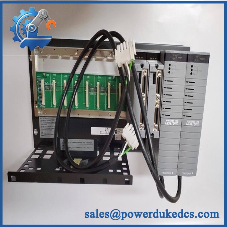
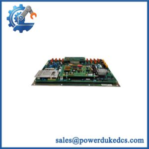
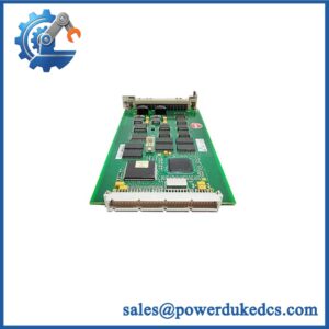
YOKOGAWA EC401-10 S2
Application Scenarios & Pain Points
A single failed ESB coupler can make an otherwise healthy FIO architecture appear unavailable. When node communication drops, engineers should first separate an hardware problem from cable, node, slot, and power issues.
Oil & Gas — Distributed FIO Cabinets
For process units using CENTUM VP, the provides the ESB connection between the FCU and field I/O node architecture. Up to 9 supported units can be connected to one under the documented configuration limits.
Chemical Processing — Redundant Control Networks
In a dual-redundant ESB arrangement, modules are installed in both designated FCU slots. This architecture provides a second ESB communication path rather than depending on one physical coupler.
Refinery Brownfield Systems
Older CENTUM installations can remain in service for many years after the original hardware procurement cycle. An exact S2 style spare is therefore useful when maintaining systems that cannot simply be converted to newer hardware during a production window.
Remote I/O Expansion
When an FCU connects to ESB node units, the provides the dedicated bus interface required for the I/O data path. Where distances or topology exceed the standard direct-ESB arrangement, Yokogawa provides optical ESB repeater hardware as a separate architecture.
High-Temperature Control Cabinets
At sustained 50°C+ ambient temperatures, inspect cabinet ventilation, connector condition, power quality, and neighboring modules. A marginal network connection can look like a failed coupler when thermal expansion or vibration is actually affecting the physical interface.
Common Error Codes & Diagnostic Symptoms
Because the -10 S2 is a communication coupler rather than a standalone CPU, exact numeric alarm codes are generated and displayed by the wider CENTUM system. The following symptoms are more reliable for hardware troubleshooting.
Symptom/Code: ESB Communication Failure / Node Offline
→ Diagnosis: Possible hardware failure, disconnected ESB cable, incorrect slot installation, node-side fault, or loss of the associated communication path.
→ Action: Check FCU diagnostics, cable integrity, slot position, and node status; replace the -10 S2 when the failure follows the coupler.
Symptom/Code: Intermittent ESB Node Loss
→ Diagnosis: A marginal connector, damaged ESB cable, unstable power source, thermal drift, or degrading interface can produce repeated node dropouts.
→ Action: Monitor both communication and physical-layer conditions during an extended test; substitute a known-good coupler if the fault tracks the module.
Symptom/Code: Redundancy Not Established
→ Diagnosis: In dual-redundant applications, one missing or incompatible can prevent the intended redundant ESB path from becoming available. Yokogawa requires installation in both slot 7 and slot 8 for dual-redundant ESB operation.
→ Action: Verify both couplers, slot assignment, style compatibility, and ESB cabling before replacing hardware.
Cross-Reference & Lifecycle Migration
Exact Variant Matters
The EC401-10 S2 should be ordered by its complete model/style designation, not simply as “.”
Yokogawa documents the family as a 1-port ESB Bus Coupler Module for N-IO/FIO in newer specifications. Supported FCU platforms include AFV30S, AFV30D, AFV40S, AFV40D, A2FV50S, A2FV50D, A2FV70S, and A2FV70D.
Related Versions
The broader family includes different style generations. They are not universally interchangeable in every system:
- Style 2 or later: Required for SEM use with Vnet/IP.
- Style S3 or later: Required for combination with the CP471 processor.
- EC402: A separate 2-port ESB Bus Coupler with different node and distance capabilities; it should not be treated as an automatic substitute for .
Installation Compatibility
For a single ESB configuration, Yokogawa specifies installation in slot 7, with slot 8 covered by a dummy module. For a dual-redundant ESB arrangement, modules are installed in both slots 7 and 8.
Firmware
he S2 is not a programmable controller that normally receives application firmware in the same manner as a PLC CPU. The key compatibility issues are hardware style, processor generation, CENTUM VP release, redundancy configuration, and ESB topology.
Lifecycle Status
Current secondary-market records identify 01-10-S2 as discontinued by the manufacturer, while Yokogawa continues to publish current -family technical documentation for newer system generations.
For an operating legacy plant, classify the specific S2 as a Limited/Legacy spare unless Yokogawa has confirmed current OEM supply for the exact required style. A tested buffer unit is advisable where the site depends on older FCU/FIO architecture.
Field Engineer’s Tech Notes
First warning: check the style number against the processor before installation. This is not a cosmetic revision. Yokogawa explicitly states that CP471 requires style S3 or later, so an S2 unit should not be presented as a universal CP471-compatible spare.
Second warning: verify the slot configuration before declaring the module defective. Single ESB uses slot 7, while dual-redundant ESB uses slots 7 and 8. A correctly functioning in the wrong configuration can still produce a system-level communication failure (this is an easy mistake during emergency maintenance).
Strict QA & Testing SOP
1. Inbound inspection
Confirm the complete YWA S2 designation, style marking, physical condition, connectors, mounting hardware, and identification label.
2. Style verification
Record the exact style number from the component tag. Compare it against the installed FCU processor configuration, especially when CP461/CP471 compatibility is relevant.
3. Mechanical inspection
Inspect the ESB connector, board edge contacts, mounting interface, and housing for bent contacts, oxidation, contamination, cracks, or impact damage.
4. Controlled installation
Mount the module into an appropriate Yokogawa FCU test environment using the specified slot arrangement. Do not energize a loose or incorrectly seated module.
5. Power-up check
Verify initialization, module status, current behavior, and controller recognition. The documented nominal current consumption is approximately 0.5 A.
6. ESB communication test
Connect a compatible ESB node and verify data communication across the bus. Confirm stable operation at the documented architecture level.
7. Node-capacity test
Where the test facility permits, exercise multiple connected node units. Yokogawa specifies a maximum of 9 connectable units for , subject to the FCS database/configuration.
8. Redundancy test
For a dual-redundant setup, verify both positions independently and confirm the expected redundant communication behavior.
9. Fault simulation
Where authorized by the test procedure, interrupt one communication path and confirm the system detects the condition correctly. Restore the path and verify recovery without unexplained module faults.
10. Extended run
Operate the module under sustained communication load while monitoring status, node connectivity, current draw, and temperature.
11. Final QC
Record serial/identification information, style code, test measurements, communication results, photographs, and technician sign-off.
12. Packaging and evidence
Use ESD-safe packaging and protect the ESB connector from mechanical damage. Supply the QC report with the unit; test videos are available to document power-up and communication testing.
Buyer’s FAQ
Q: Can I use an EC402 insof S2?
A: Not as an automatic substitution. EC402 is a different two-port ESB Bus Coupler with different node and transmission-distance characteristics. The installed FCU architecture must be checked before considering migration.
Q: Is S2 compatible with ?
A: Not according to Yokogawa’s current specification. Yokogawa states that only style S3 or later of can be combined with the processor.
Q: Can I hot-she S2?
A: Do not assume live replacement is permitted merely because the ESB architecture can be redundant. Physical removal can affect the active communication path, and the approved maintenance procedure depends on the FCU’s redundancy configuration. Follow the site-specific Yokogawa procedure before removing the coupler.
Q: How do I verify a “New Orl” S2?
A: Request clear photographs of the Yokogawa identification label, exact S2 style marking, connector interfaces, and packaging. For legacy inventory, request a documented power-up and ESB communication test rather than relying solely on a condition label.



 Start Chat


