

Description
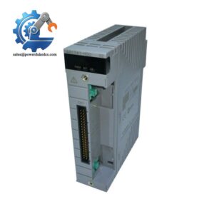
- Model: PW482-10 S2
- Brand: Yokogawa
- Series: PW481 / PW482 / PW484 Power Supply Module
- Part Type: AC-input DCS power supply module
- Core Function: Provides dedicated system power for Yokogawa FCU, FIO Node Unit, and Optical ESB Bus Repeater Unit installations.
- Key Specs: 220–240 VAC input; 50/60 Hz ±3 Hz; 5.1 VDC / 7.8 A and 24 VDC / 1.7 A outputs; maximum power consumption 230 VA; exclusive system connector.
- Lifecycle: Legacy / discontinued according to current secondary-market records; Yokogawa’s official specification confirms the S2 hardware family.
Product Introduction
A power-supply failure can take an otherwise healthy Yokogawa node out of service without damaging a single I/O channel. The PW482-10 S2 belongs to Yokogawa’s PW482 family and is used with Field Control Units, FIO Node Units, and Optical ESB Bus Repeater Units. Yokogawa specifies the PW482 for 220–240 VAC ±10%, at 50/60 Hz ±3 Hz, with a maximum power consumption of 230 VA. The S2 configuration also provides the system’s specified 5.1 VDC and 24 VDC rails, rather than functioning as a general-purpose cabinet power supply.
For maintenance teams, that distinction matters. Current technical records identify the PW482-10 S2 output as 5.1 VDC at 7.8 A and 24 VDC at 1.7 A, with an approximate weight around 0.9–1.0 kg. A like-for-like replacement can preserve the existing FCU or node architecture and avoid rewiring around an unrelated power supply (particularly important where a redundant supply arrangement is already engineered). Yokogawa states that two PW48x modules can be installed for dual redundancy.
Core Technical Specifications
| Parameter | Value |
|---|---|
| Manufacturer | Yokogawa |
| Model | PW482-10 S2 |
| Series | PW482 |
| Product Type | Power Supply Module |
| Primary Application | FCU, FIO Node Unit, Optical ESB Bus Repeater Unit |
| Input Voltage | 220–240 VAC |
| Input Voltage Tolerance | ±10% |
| Input Frequency | 50/60 Hz ±3 Hz |
| Input Current | Approximately 1.3 A |
| Output 1 | 5.1 VDC / 7.8 A |
| Output 2 | 24 VDC / 1.7 A |
| Maximum Power Consumption | 230 VA |
| Interface | Exclusive Yokogawa system connector |
| Redundancy | Two modules can be installed for dual-redundant operation |
| Hardware Style | S2 |
| Explosion Protection | Basic -10 configuration; no explosion protection indicated |
| Weight | Approximately 1 kg |
| Operating Temperature | Dependent on the specified PW48x installation environment; verify the exact system configuration before field use |
| Replacement Classification | Legacy / secondary-market spare |
Yokogawa’s official GS identifies as the 220–240 VAC member of the PW48x family and specifies 230 VA maximum power consumption and approximately 1 kg weight. Current equipment records provide the detailed 5.1 VDC/7.8 A and 24 VDC/1.7 A output values for -10 S2.
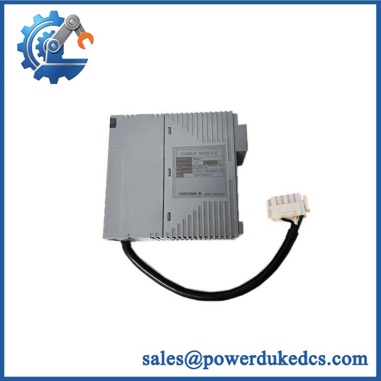
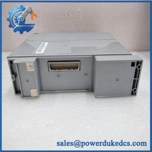
Yokogawa PW482-10 S2
Application Scenarios & Pain Points
In a CENTUM control cabinet, loss of the can remove power from an FCU or associated node even when the controller and I/O cards have no fault. A verified replacement restores the intended power architecture without redesigning the cabinet.
For FIO Node Units, the key issue is electrical matching. The -10 S2 is designed around Yokogawa’s dedicated connector and system rails, so replacing it with a generic supply requires much more than matching “24 VDC.” The module provides both 5.1 VDC and 24 VDC outputs in the documented configuration.
During refinery or chemical-plant turnaround work, a spare can reduce exposure to an extended node outage. Yokogawa also supports dual-redundant installation by using two compatible PW48x modules.
For legacy control-system maintenance, procurement becomes difficult when an old power module is needed immediately but normal factory replenishment is no longer available. Current secondary-market records classify S2 as discontinued, while specialist suppliers continue to list it.
At elevated cabinet temperatures, inspect the power module for thermal aging before returning it to service. Power electronics exposed to sustained high temperature can show capacitor, solder-joint, and connector deterioration long before an obvious external failure appears.
🚨 Common Error Codes & Diagnostic Symptoms
Symptom/Code: FCU power alarm / node does not start
→ Diagnosis: Possible internal power-conversion failure, loss of incoming 220–240 VAC, or a defective system connector.
→ Action: Verify the AC supply first, then measure the specified output rails; replace the module if the outputs remain outside tolerance.
Symptom/Code: Repeated FCU resets or intermittent node dropouts
→ Diagnosis: An unstable 5.1 VDC or 24 VDC rail can cause repeated controller or I/O disturbances.
→ Action: Monitor both output rails under representative load and replace the if instability follows the module.
Symptom/Code: Redundant power-supply alarm
→ Diagnosis: One member of a dual-redundant PW48x pair may have lost its output or developed abnormal operating behavior.
→ Action: Test each module independently using the approved Yokogawa maintenance procedure and replace the failing unit.
The is a dedicated system power module, so troubleshooting is generally performed through system diagnostics and measured electrical behavior rather than a standalone numeric fault-code list.
🚨 Cross-Reference & Lifecycle Migration
Lifecycle Status: Legacy / Obsolete in secondary-market records.
A current specialist inventory record explicitly describes -S2 as discontinued by the manufacturer, while other suppliers continue to list new and refurbished units. Yokogawa’s official documentation, meanwhile, confirms the S2 family and its role within the FCU/FIO/Optical ESB architecture.
Compatibility Assessment
- S2ent82-10 S2: Direct like-for-like replacement after electrical and connector verification.
- PW481- → S2: Not a direct substitute. PW481 is the 100–120 VAC family, whereas is 220–240 VAC.
- PW484- → S2: Not a direct substitute. PW484 is the 24 VDC-input member of the PW48x family.
- -50us : Do not assume equivalence. The complete suffix identifies a different configuration and must be matched against the installed system.
- Firmware flashing: Not applicable to the power-supply function.
- Hardware modification: Normally unnecessary for an idal S2 replacement.
- Buffer-stock strategy: Because current records identify this model as discontinued, critical installations should maintain a verified spare rather than depend on future factory availability.
Field Engineer’s Tech Notes
First warning: never approve the replacement based only on “.” PW481, , and PW484 use different input-power families. A requires 220–240 VAC, while PW481 uses 100–120 VAC and PW484 uses 24 VDC. Check the complete nameplate before energization.
Second warning: measure both output rails.he S2 is documented with 5.1 VDC / 7.8 A and 24 VDC / 1.7 A outputs. A module that produces one rail correctly but has a degraded second rail can create intermittent system symptoms that look like a controller or I/O failure. (This is a common diagnostic trap in aging DCS cabinets.)
Strict QA & Testing SOP
- Inbound inspection: Verify Yokogawa markings, complete identifier, packaging, quantity, and visible condition.
- Nameplate verification: Confirm the 220–240 VAC input configuration and exact S2 designation.
- Physical inspection: Examine the enclosure, system connector, ventilation openings, mounting surfaces, PCB condition, labels, and signs of overheating or corrosion.
- Revision recording: Capture serial number, date code, hardware revision, and visible manufacturing identifiers.
- ESD-controlled handling: Use grounded handling procedures for the electronic assembly.
- Pre-power electrical check: Inspect for abnormal shorts, damaged components, contaminated contacts, and mechanical connector defects.
- Controlled AC power-up: Apply a controlled 220–240 VAC input within the Yokogawa specification and monitor startup behavior.
- 5.1 VDC output test: Measure output voltage under no-load and representative-load conditions; verify stable behavior.
- 24 VDC output test: Measure the second output rail and confirm stable voltage under representative load.
- Current/load verification: Test against controlled loads up to the documented 7.8 A / 5.1 VDC and 1.7 A / 24 VDC output ratings using an approved laboratory procedure.
- Ripple/noise observation: Check output stability and abnormal ripple where suitable test equipment is available.
- Redundant-operation test: With a compatible FCU/node test arrangement, verify operation of two installed PW48x modules and confirm expected redundancy behavior. Yokogawa documents dual-redundant installation using two modules.
- Power-cycle test: Perform controlled startup/shutdown cycles and confirm repeatable output recovery.
- Thermal observation: Monitor temperature rise under representative load and inspect for abnormal heating.
- Connector integrity test: Verify secure mechanical engagement and check for intermittent contact.
- Final QC release: Record input voltage, both output measurements, load current, test duration, revision information, photographs, and inspector approval.
- Packaging: Use ESD-safe protection with connector shielding and shock-resistant outer packaging.
- Test evidence: Test videos are available for applicable electrical and system-level inspections.
Yokogawa’s official specification confirms the 230 VA maximum consumption, exclusive connector, and dual-redundant installation capability of the family.
Buyer’s FAQ
Q1. Can I hot-she S2 while the Yokogawa FCU is running?
A: Do not assume that redundancy means the module is universally hot-swappable. Follow the approved Yokogawa maintenance procedure for the exact FCU or FIO Node Unit. Confirm that the remaining power module can safely support the connected load before removing one unit.
Q2. How can I verify a New Oal S2?
A: Match the complete nameplate, inspect the Yokogawa labeling and connector, record the hardware revision, and perform controlled electrical testing. The most important electrical checks are the 220–240 VAC input and the two documented output rails.
Q3. Can I substitute PW481 or PW484?
A: Not as a direct replacement. is the 100–120 VAC input version, is 220–240 VAC, and is the 24 VDC input version. The installed system’s complete part number must control procurement.
Qes S2 require firmware flashing after replacement?
A: No firmware flash should normally be required because this is a dedicated power-supply module, not a processor or communications controller. The critical checks are electrical configuration, connector compatibility, load capacity, and stable operation after installation.
Q5. What warranty should procurement require?
A: Require written coverage for DOA and functional failure, the warranty duration, return authorization procedure, inspection window, and return freight terms. For discontinued inventory, also require confirmation of the exact suffix, hardware revision, condition, test status, and actual-stock availability before the PO is released.



 Start Chat


