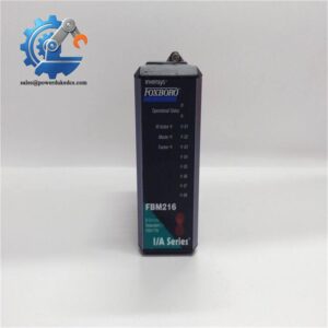
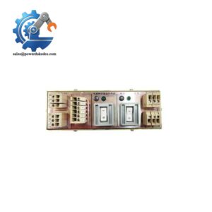
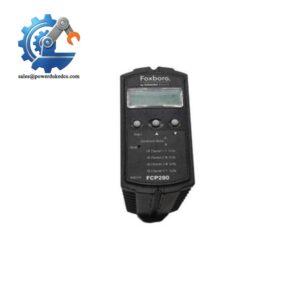
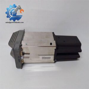
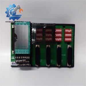
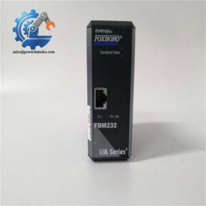
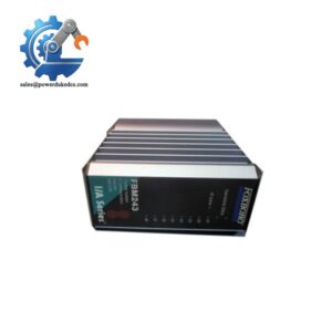
Description
- Brand: Foxboro
- Full Model Number: CP60 — control processor designation; confirm the exact orderable module code before purchase
- System/Series Family: Foxboro I/A Series Distributed Control System
- Core Function: Regulatory, logic, timing, and sequential control; fieldbus data acquisition; alarm detection and notification
- Top 3 Technical Specifications:
- Fieldbus: 10 Mbps Ethernet trunk for the documented CP60 architecture
- I/O Capacity: Up to 120 Fieldbus Modules, subject to scan periods and system configuration
- Processing: Up to 4,000 configured control blocks; typical execution rate of 3,400 blocks per second in the published specification
- Stock Status: Subject to physical inventory verification
- Available Condition: New Original, New Surplus, or Tested Used, according to actual stock
- Fault-Tolerant Configuration: Two single-width processor modules operating in parallel
- Simplex Alternative: CP60S single-width processor configuration
- Warranty: Coverage and duration confirmed in the sales quotation
Technical Product Introduction
A control processor failure can interrupt regulatory loops, sequencing, alarm processing, and communication with field I/O. The Foxboro CP60 is designed for the I/A Series DCS, where configured control algorithms execute alongside connected Fieldbus Modules (FBMs). Its responsibilities include process-variable control, data acquisition, and alarm handling. In a legacy plant, the key maintenance decision is whether the fault lies in the processor, Nodebus connection, Ethernet trunk fieldbus, or an associated communications module. Replacing the wrong component wastes shutdown time and can introduce new configuration problems.
The published CP60 specification lists a 50 ms minimum block processing cycle, a maximum of 4,000 configured blocks, and support for up to 120 FBMs, depending on the selected scan periods. Typical execution is specified at 3,400 blocks per second. Those figures provide useful engineering reference points when evaluating the existing control workload; actual performance depends on block types, scan schedules, and the installed system configuration. Unlike a simplex installation, the fault-tolerant CP60 arrangement uses two single-width processor modules operating in parallel. The CP60S, by comparison, is the documented simplex variant. Treat these configurations as distinct procurement requirements (the exact module part number, hardware revision, software compatibility, and installed redundancy arrangement must be confirmed before ordering).
Application Scenarios & Field Realities
- Refinery process regulation: In distillation and separation units, control loops rely on continual measurement updates from field instruments. When investigating erratic control or missing measurements, check processor diagnostics alongside FBM status and fieldbus communication before replacing the CP60.
- Boiler and utility control systems: Sequencing, interlocks, and alarm handling depend on the configured control strategy and its associated field I/O. During processor replacement planning, record the active control configuration and verify the expected startup and recovery behavior before returning affected equipment to operation.
- Chemical reactor and batch-process control: Cascade regulation, timed sequences, and alarm conditions can depend on numerous interrelated control blocks. Review block execution periods and processor loading when investigating missed deadlines or abnormal scan behavior; processor capacity alone does not establish that a particular application will meet its timing requirements.
- Legacy DCS integration projects: Where supported migration interfaces connect other control-system I/O families to an I/A Series installation, the processor must match the approved fieldbus and migration configuration. Confirm the interface modules, communication paths, and supported device configuration before commissioning a replacement.
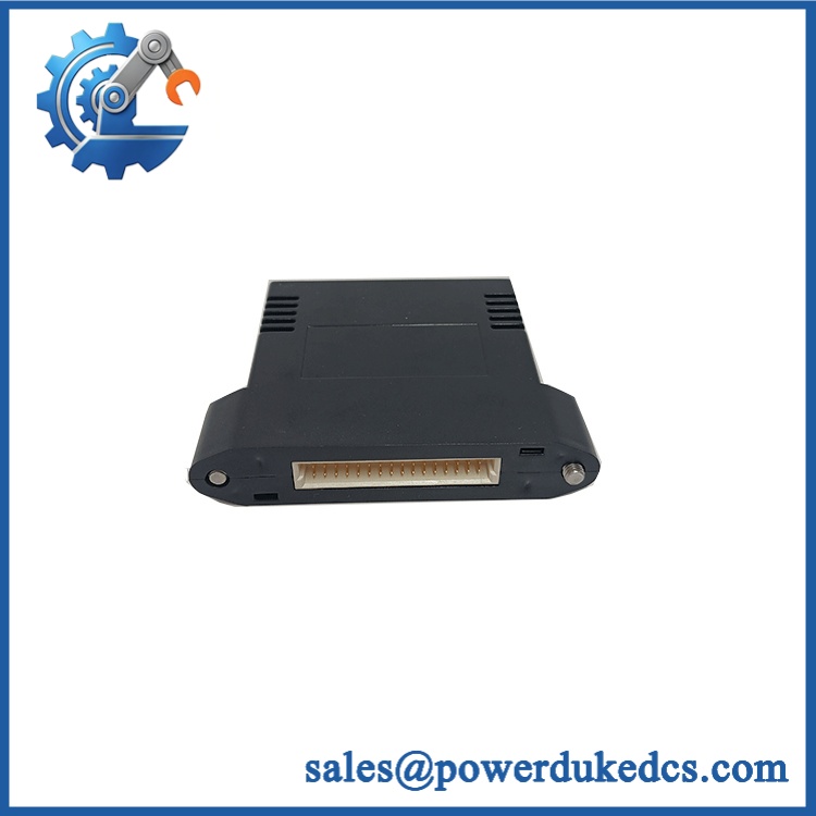
Foxboro CP60
Quality Assurance SOP
The following inspection and testing protocol is intended for pre-shipment verification of a Foxboro processor module. Tests should be recorded against the actual orderable part number, revision, and condition. Full fault-tolerant testing requires an appropriate paired configuration and compatible test environment.
| QA Stage | Inspection and Test Procedure | Acceptance Criteria |
|---|---|---|
| Part Identification | Check the model designation, full part number, revision markings, serial information where available, and applicable reference documentation. | Part identity matches the confirmed order and intended system configuration. |
| OEM Authenticity Inspection | Examine labels, housing construction, connectors, mounting interfaces, fasteners, and visible manufacturing markings. Review available traceability records. | No unexplained alterations, damaged interfaces, or unresolved identification discrepancies. |
| Mechanical Inspection | Inspect the enclosure, connector contacts, retention features, mounting edges, and fault-tolerant connector interface where applicable. | No visible damage that compromises mounting, electrical connection, or safe operation. |
| Power Input Verification | Check the intended power-source rating against the applicable processor specification and cabinet drawings. Inspect the power connections before energization. | Supply arrangement matches the verified hardware requirements; no unintended wiring changes. |
| Power-On Self-Test (POST) | Energize the processor in a compatible test setup and observe the documented startup diagnostic sequence. Inspect the red and green front-panel status indicators. | Expected startup progression with no unexplained diagnostic fault. Interpret LED states using the applicable hardware manual rather than assuming universal ERR/RUN labels. |
| Processor Diagnostics | Review available power-up self-checks, runtime diagnostics, watchdog monitoring, and fault messages. | Expected processor initialization and no unresolved hardware diagnostic alarms. |
| Nodebus Communication Test | Connect the processor to a compatible I/A Series test environment and verify communication with the configured control-system nodes. | Expected communication status and no unexplained Nodebus errors. |
| Ethernet Trunk Fieldbus Verification | Check the required interface modules, physical connections, and communication status using the approved test topology. | Fieldbus communication established without unexplained link or address-verification faults. |
| FBM Communication Handshake | Connect representative compatible FBMs and verify discovery, communication, and data exchange through the configured fieldbus interface. | Expected module status and correct exchange of test data under the test configuration. |
| Control-Block Execution Test | In a suitable test environment, execute representative logic, timing, and control blocks. Check scheduled execution and resulting values against the test specification. | Expected block execution and output values; no unexplained processing or configuration errors. |
| Fault-Tolerance Verification | Where the supplied configuration and test equipment support it, verify processor-pair status, interconnecting hardware, fault indication, and documented failover behavior. | Expected behavior under the approved fault-tolerance test procedure. Single-module testing does not establish pair-level redundancy. |
| Final Inspection and Packing | Record the model, revision, condition, diagnostics, tests performed, and any limitations. Protect connectors and mounting interfaces during packaging. | Unit identification and test scope documented; hardware protected against handling and transport damage. |