Description
- Brand: Foxboro (Schneider Electric)
- Full Model Number: E69F-BI2
- System/Series Family: E69F Field-Mounted Current-to-Pneumatic Converter
- Core Function: Converts an analog DC current command into a proportional pneumatic control signal
- Top 3 Technical Specs: 4–20 mA DC input; 170 Ω input impedance; 3–15 psi (20–100 kPa) pneumatic output
- Enclosure: Bolted-cover weatherproof housing for non-explosionproof applications
- Performance: ±1.0% of span accuracy for output code 2
- Mounting: Valve yoke, flat surface, or nominal DN 50 (2-inch) vertical pipe
- Approximate Unit Weight: 2.3 kg
- Lifecycle Status: Legacy model; IP26 series identified in available product listings as a successor option
- Stock Status: Quote-based availability; unit condition, inspection records, and warranty terms confirmed before order
Technical Product Introduction
When a pneumatic control valve stops responding correctly, the fault may sit between the controller’s analog output and the valve’s pneumatic actuator. The Foxboro E69F-BI2 addresses this interface by converting a 4–20 mA DC input into a proportional 3–15 psi pneumatic signal. Designed for field installation, it supports industrial control loops that require electrical command signals to operate pneumatic instruments or valve assemblies. Its bolted-cover enclosure is intended for weatherproof service in non-explosionproof applications.
With a nominal input impedance of 170 Ω and output code 2, the E69F-BI2 supports the 20–100 kPa output range. Published performance specifications give accuracy of ±1.0% of span, typical linearity of ±0.5% of span, and typical repeatability of ±0.25% of span. These figures provide useful acceptance criteria during commissioning and spare-part qualification. Unlike digital valve positioners, this instrument performs analog current-to-pressure conversion without a digital communication interface or programmable scan cycle. Direct or reverse action must match the installed control loop (confirm the actual configuration against the nameplate and calibration records before replacement).
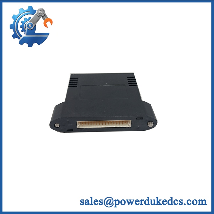
Foxboro E69F-BI2
Application Scenarios & Field Realities
- Refinery process control: Where distillation-column or fractionation valves receive 4–20 mA commands from a distributed control system, the E69F-BI2 can provide the corresponding pneumatic signal when the actuator arrangement requires a 3–15 psi input. Confirm the valve’s specified signal range before installation.
- Boiler and utility control loops: When maintaining pneumatic feedwater, steam-bypass, or pressure-control valve assemblies, technicians can use the model’s published input impedance and output range as test-bench reference points. Verify the actual valve positioning arrangement; an I/P converter does not replace a separate positioner unless the equipment design specifically permits it.
- Legacy plant instrumentation: For older installations retaining analog control outputs and pneumatic final elements, the E69F-BI2 offers a potential like-for-like spare path when the complete model configuration matches. The enclosure, mounting orientation, pneumatic connections, and operating action all matter.
- Split-range valve applications: Where two control valves share a split-range signal, confirm whether the required input is 4–12 mA or 12–20 mA. The family supports these input arrangements, but the replacement’s actual calibration and direct or reverse action must be verified before the loop is returned to service.
Migration, Compatibility & Installation Traps
Replacement Matrix
| Replacement Path | Classification | Engineering Requirements |
|---|---|---|
| Identical Foxboro -BI2 configuration | Drop-in Replacement — Conditional | Match input range, output range, direct/reverse action, enclosure, mounting, connections, and any installed options. Verify the nameplate and recalibrate before commissioning. |
| Foxboro IP26-1000 series | Hardware Modification Required — Pending Verification | Treat as a migration project until mechanical dimensions, mounting hardware, pneumatic fittings, signal characteristics, and required approvals have been checked against the installed unit. |
| Existing PLC or DCS analog output | Software Compatible — Conditional | No converter firmware migration is involved. Existing scaling may remain unchanged if the 4–20 mA range, signal action, and pneumatic output mapping are identical. Validate the loop configuration during commissioning. |
The IP26 series is a potential successor for legacy installations, but a shared current-to-pneumatic function does not establish dimensional or certification equivalence. Obtain the applicable product specifications before approving a substitution.
Field Traps to Check Before Installation
- Enclosure and hazardous-area classification: The B designation specifies a bolted-cover weatherproof enclosure for non-explosionproof applications. Do not substitute this configuration where an explosionproof enclosure is mandatory. Check the complete model code, nameplate, and installation-area approval requirements before energizing the loop.
- Supply pressure and signal action: Output code 2 specifies a 3–15 psi range, with a nominal supply pressure of 20 psi in the published specification. Supply pressure must remain at least 3 psi above the maximum output pressure. Use clean, dry instrument air free from oil, dust, and water. Confirm direct or reverse action and any split-range configuration before adjusting zero and span.
Quality Assurance SOP
Each unit should be assessed against its actual model code, physical condition, and documented operating configuration. A model number alone does not establish that a legacy instrument is suitable for immediate installation.
Incoming Inspection and Identification
- OEM anti-counterfeit visual inspection: Compare nameplate information, model designation, manufacturer markings, enclosure construction, and available identification records against the applicable Foxboro product documentation.
- Physical condition assessment: Inspect the housing, cover fasteners, electrical entry, pneumatic ports, threaded connections, and mounting points for corrosion, impact damage, contamination, or unauthorized modification.
- Configuration verification: Record the full model designation, input range, output range, direct/reverse action, enclosure type, installed options, and any available calibration documentation.
Bench Testing and Functional Verification
- Calibrated instrumentation: Use a calibrated DC current source or loop calibrator, a suitable pressure reference, and a regulated supply of clean, dry instrument air.
- Input-to-output verification: Apply 4 mA, 12 mA, and 20 mA input points and record the corresponding pneumatic output. For direct action, the expected nominal outputs are 3 psi, 9 psi, and 15 psi, respectively. For reverse action, verify the inverse response against the unit’s documented configuration.
- Accuracy assessment: Compare measured output against the manufacturer’s published accuracy specification of ±1.0% of span for output code 2, using the specified test conditions.
- Zero and span checks: Record the initial readings, adjust only when required and permitted by the applicable procedure, and document the final results.
- Pneumatic integrity: Check for abnormal leakage, unstable pressure, restricted flow, and failure to maintain the required output at the test points.
- Power-on self-test and ERR/RUN LEDs: Not applicable to this electropneumatic instrument. It is not a processor-based control module with these status indicators.
- Communication handshake verification: Not applicable because has no digital communication interface. Its functional verification is based on the relationship between input current and pneumatic output.
Pre-Shipment Release
Before dispatch, retain the unit identification record, inspection checklist, measured input/output results, physical-condition photographs, and applicable warranty terms. Record any deviations rather than reporting the unit as fully tested without supporting results.
Release criterion: Ship only after the model configuration has been matched to the customer’s requirement and all specified acceptance tests have been completed with acceptable documented results.