Description
- Brand: Foxboro
- Full Model Number: 0399144
- Associated Part Numbers: SY-0301059F; SY-1025115C; SY-1025120E
- System / Series Family: Foxboro distributed control system (DCS); exact platform and hardware revision require confirmation
- Core Function: Multi-board control assembly associated with Foxboro DCS hardware; exact board-level functions must be verified against the installed assembly.
- Top 3 Technical Specifications: Multi-board assembly identification; associated control/interface boards SY-1025115C and SY-1025120E; associated power sub-board SY-0301059F, subject to physical verification
- Electrical Specifications: Supply voltage, output rails, power consumption, and connector assignments require confirmation from the applicable hardware documentation.
- Lifecycle Status: Legacy hardware sourcing; current OEM manufacturing status requires confirmation
- Stock Status: Available quantity, condition, revision, completeness, and test status require written confirmation
Commercial-Technical Deep Dive
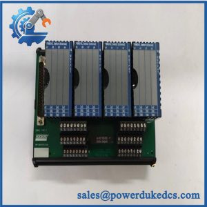
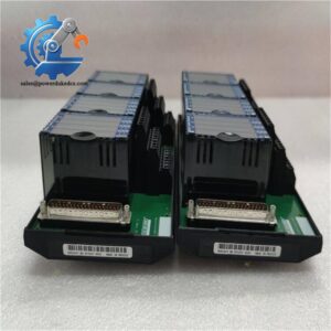
When an existing Foxboro DCS requires a replacement control-board assembly, mismatched subassemblies can delay maintenance and extend an unplanned outage. The Foxboro 0399144 assembly, identified alongside SY-0301059F and SY-1025115C/SY-1025120E, is described in supplier listings as a multi-board industrial control assembly. These identifiers must be treated as a related set until the installed hardware and applicable documentation confirm the exact assembly configuration. SY-0301059F is associated with a power-supply sub-board, while the precise functions and interfaces of SY-1025115C and SY-1025120E require revision-specific verification. For procurement teams, the immediate priority is to match the complete assembly rather than purchase an individual board based on a partial part number.
Replacing the correct assembly may preserve an existing control cabinet, established field wiring, and the installed DCS architecture. That can reduce the engineering and commissioning costs associated with a broader hardware migration. Calculate total cost of ownership (TCO) using the replacement price, maintenance labor, diagnostic testing, process downtime, and any required configuration work. For preliminary planning, allow 2–4 maintenance labor hours for a straightforward physical replacement and initial verification; additional engineering or commissioning may be necessary. This is a planning estimate, not a manufacturer-specified installation time. Before approving the purchase, obtain actual-unit photographs, confirm the relationship among all four identifiers, and verify that the offered assembly contains every required board (especially where the original equipment uses a specific revision or matched set).
Compatibility & Installation Traps
Migration and Compatibility
| Replacement Scenario | Classification | Required Action | Preliminary Time Allowance |
|---|---|---|---|
| Exact 0399144 assembly with matching sub-board references and revision | Conditional drop-in replacement | Match all board identifiers, connectors, mounting points, and the installed system configuration. | 2–4 maintenance labor hours |
| Same main assembly number with a different sub-board revision | Engineering verification required | Check board revisions, electrical interfaces, documented substitutions, and system compatibility. | 2–4 engineering hours for initial review |
| Individual SY-0301059F, SY-1025115C, or SY-1025120E offered separately | Not automatically equivalent to the complete assembly | Confirm the bill of materials and whether the purchase requires the complete assembly or a specific sub-board. | Estimate after parts verification |
| Alternative Foxboro board assembly proposed as a replacement | Not an automatic drop-in replacement | Verify the system platform, electrical characteristics, connector assignments, and supported configuration. | Site-specific estimate required |
Replacement classification: A drop-in replacement cannot be confirmed from the supplied identifiers alone. A firmware flash or logic rewrite should not be assumed necessary, but neither should it be ruled out until the installed platform and approved replacement documentation have been checked.
Field Traps to Check Before Ordering
- Incomplete assembly: Confirm whether 0399144 identifies the complete set or an assembly-level reference. Verify that SY-0301059F, SY-1025115C, and SY-1025120E are all included when required by the original installation.
- Power and connector mismatch: Do not rely on general supplier descriptions for voltage, pin assignments, or output rails. Match the actual nameplate, board revision, and approved electrical drawings before energizing the replacement.
Hot-swap warning: Do not assume this assembly supports energized removal. Unless the applicable Foxboro instructions explicitly authorize live replacement for the installed configuration, use the prescribed shutdown and isolation procedure. If removing the assembly could interrupt a control or protective function, establish the required safe state before disconnecting any board or cable.
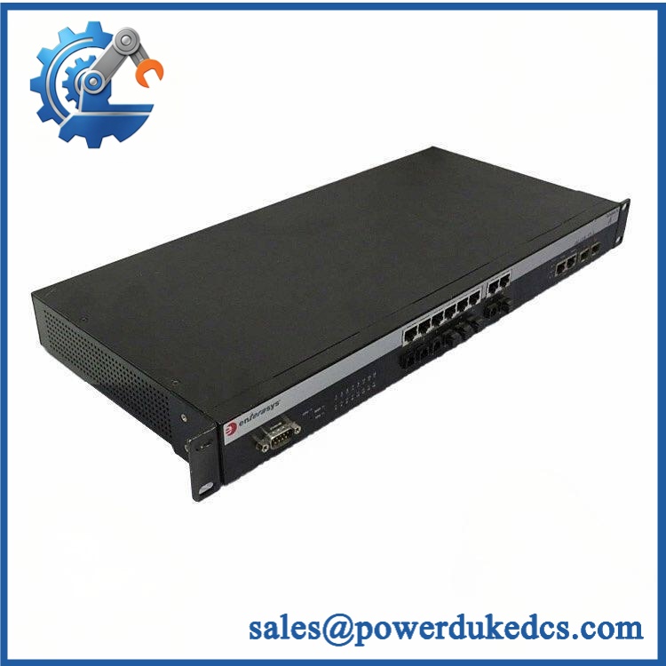
Foxboro 0399144 SY-0301059F
Quality Assurance SOP
The following procedure defines a proposed pre-shipment quality-assurance scope for Foxboro 0399144 inventory. Testing must be appropriate to the actual assembly and its documented function. Any test not completed must be disclosed in the inspection report.
Visual Inspection and Part Authentication
- OEM anti-counterfeit visual inspection: Examine manufacturer markings, part-number labels, serial or production details, and available traceability records.
- Assembly identification: Verify 0399144 and each associated sub-board number against the purchase specification.
- Revision verification: Record the revision shown on every accessible board label.
- Physical condition: Inspect PCBs, connectors, mounting features, components, and solder joints for corrosion, contamination, impact damage, or unauthorized rework.
- Assembly completeness: Confirm the quantity and identity of included boards, connectors, and other specified components.
- Photographic documentation: Capture the overall assembly, individual board markings, connectors, and visible condition before packaging.
Power-On and Diagnostic Testing
- Confirm the documented supply requirements and compatible test fixture before energization.
- Conduct a controlled power-on self-test (POST) when supported by the assembly and applicable procedure.
- Check RUN, ERR, POWER, or other status indicators where fitted and documented for the specific hardware revision.
- Record startup behavior, diagnostic messages, supply measurements, and any abnormal indications.
- Verify that the compatible host system recognizes the assembly where applicable.
- Do not energize boards with unidentified power requirements or unsupported terminal assignments.
Functional and Interface Verification
- Board-level verification: Test each sub-board according to its documented function and approved acceptance criteria.
- Power verification: Where SY-0301059F is confirmed as the power sub-board, measure its specified outputs using suitable calibrated instruments and the correct test arrangement.
- Communication handshake verification: Where the assembly provides a documented communications interface, verify communication with compatible test equipment or a supported host system.
- Signal-path checks: Exercise supported control or interface functions using the approved procedure.
- Diagnostic review: Record observable faults and confirm that no unexplained diagnostic indication remains.
- Test evidence: Document the equipment, measured values, test conditions, and results. Do not represent the complete assembly as fully function-tested when only individual boards have been inspected.
Final Acceptance and Shipment Release
- Match the tested assembly against the purchase order and approved parts list.
- Verify that the agreed sub-boards and accessories are present.
- Provide actual-unit photographs and the agreed inspection or functional-test report.
- Identify tests that were not performed and any limitations of the test setup.
- Package the boards with appropriate electrostatic-discharge protection and mechanical protection.
- Release the assembly only after the agreed acceptance requirements have been met.
Testing limitation: Bench testing cannot establish the correct operation of the complete installed DCS. Site acceptance may require verification of the host system, power distribution, communications, configuration, and associated control functions.
CRO-Driven Buyer FAQ
Is Foxboro 0399144 obsolete, and can genuine replacement stock still be sourced?
The current manufacturing status of this exact assembly requires confirmation. Existing inventory may vary by condition, revision, and assembly completeness. Request written stock confirmation, actual-unit photographs, available traceability records, and the complete part numbers of all included boards before issuing the purchase order.
Can the 0399144 assembly be replaced while the DCS remains online?
Do not assume hot-swap capability. The applicable hardware documentation and the site’s approved maintenance procedure must explicitly permit energized replacement for the installed configuration. Otherwise, arrange the required shutdown and isolation, assess affected control functions, and follow the site’s change-control requirements.
Do all four identifiers need to match when ordering a replacement?
Confirm the relationship among 0399144, SY-0301059F, SY-1025115C, and SY-1025120E against the installed assembly. If the original equipment requires a matched multi-board set, an individual sub-board may not satisfy the replacement requirement. Request a component-level inventory list and photographs of the actual assembly.
What warranty and technical support terms should be confirmed?
Agree on the warranty period, commencement date, defect coverage, exclusions, return authorization procedure, and deadline for reporting a defective-on-arrival unit. Confirm whether support covers hardware inspection only or also includes functional testing and installation troubleshooting. Do not assume that surplus stock carries the original manufacturer’s warranty.
What information should engineering provide before approving the purchase?
Provide the installed assembly’s full identification labels, visible revisions, host system designation, relevant wiring diagrams, and the required board-level bill of materials. Confirm electrical requirements and any approved replacement references before purchase. These records reduce the risk of receiving an incomplete or incompatible assembly and help establish a clear acceptance procedure.