Description
- Brand: Foxboro
- Full Model Number: CP30 Control Processor 30; commonly identified by part number P0960AW
- System/Series Family: Foxboro I/A Series Distributed Control System
- Core Function: Regulatory control, logic execution, timing, sequential control, process data acquisition, and alarm detection
- Top 3 Technical Specs: Intel 386 microprocessor; 4 MB storage; EIA RS-485 fieldbus communication at 268.75 Kbps
- Fieldbus Capacity: Up to 24 Fieldbus Modules on the local bus; up to 64 on supported extended configurations
- Power Requirements: 39 V DC typical; 15 W maximum per non-fault-tolerant module
- Operating Environment: 0–60°C; 5–95% relative humidity, noncondensing
- Stock Status: Availability, hardware revision, physical condition, and testing status confirmed against the actual unit before shipment
Technical Product Introduction
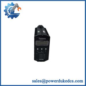
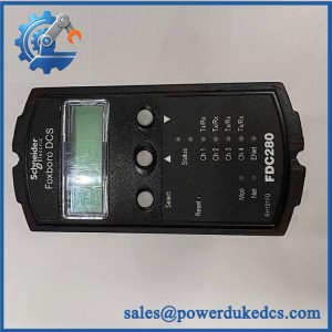
When a legacy DCS processor fails, multiple control loops and associated field I/O operations can become unavailable. The Foxboro CP30 Control Processor 30 performs regulatory, logic, timing, and sequential control functions within the I/A Series architecture. It also handles process data acquisition, alarm detection, and alarm notification through its configured control environment. For maintenance teams supporting established process plants, replacing a failed CP30 can preserve the existing control strategy and fieldbus arrangement without forcing an immediate system-wide migration. The exact hardware identity matters: P0960AW is a commonly associated part number, but the installed unit’s nameplate and revision should determine the final procurement specification.
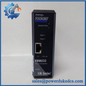
For the documented CP30 hardware generation, the OEM specification identifies an Intel 386 processor, 4 MB of storage, and fieldbus transmission at 268.75 Kbps. Local fieldbus connections can extend up to 10 m and support up to 24 FBMs; supported extended configurations can accommodate up to 64 FBMs over twinaxial cable distances of 1,800 m or fiber-optic distances of 20 km. The extended configurations require the appropriate interface equipment (isolators, modems, and other components depend on the architecture). Power consumption is rated at a maximum of 15 W per non-fault-tolerant module. These documented values provide a practical baseline for legacy system maintenance, but they should not be applied automatically to a different processor style or hardware revision.
Application Scenarios and Field Realities
- Refinery process-control stations: When a CP30 failure affects interconnected pressure, flow, and temperature loops, identify the affected control station and verify the processor revision before installation. After replacement, confirm control-strategy execution and representative process values before returning loops to automatic control.
- Power-generation auxiliary controls: Pump sequencing, permissive logic, and equipment interlocks may depend on the CP30’s configured logic functions. During a planned outage, confirm that the replacement matches the existing hardware configuration and that required control compounds and system configuration records are available.
- Chemical processing and batch operations: Where sequential control coordinates feed valves, transfer pumps, and process permissives, a processor replacement can involve more than restoring power. Verify the loaded configuration, alarm handling, fieldbus status, and sequence behavior against the approved commissioning procedure.
- Distributed I/O installations: For systems with remote FBM enclosures, the physical fieldbus medium is a critical engineering consideration. A supported fiber-optic configuration can extend the fieldbus to 20 km, compared with 1.8 km for the documented twinaxial arrangement. Confirm isolator placement, modem requirements, cable routing, and installed termination hardware before diagnosing a communication failure as a defective processor.
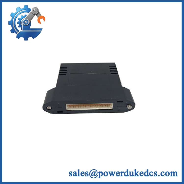
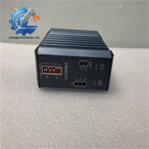
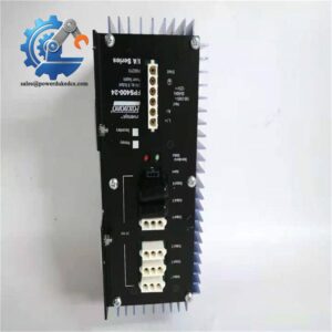
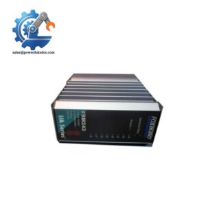
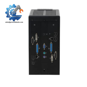
Foxboro CP30
Migration Compatibility and Installation Traps
Replacement Compatibility Matrix
| Replacement Category | Engineering Guidance |
|---|---|
| Drop-in Replacement | Conditional; a matching part number and compatible revision may support a like-for-like replacement when the existing hardware and software configuration are retained |
| Software Compatibility | Verify the installed I/A Series release, processor configuration, control software, and applicable licensing requirements |
| Hardware Modification Required | May be required when changing processor styles, fault-tolerance configurations, mounting arrangements, or fieldbus interfaces |
| Style B Substitution | Do not assume interchangeability; check the complete part number, hardware style, and associated configuration requirements |
| Fault-Tolerant Operation | The documented fault-tolerant configuration uses two single-width processor modules with interconnecting X-bus and Z-bus connections |
| Newer-Generation Migration | A transition to a newer processor architecture requires a documented compatibility and migration assessment; physical fit alone is insufficient |
| Configuration Restoration | Verify control compounds, system configuration, software licensing, and fieldbus assignments before commissioning |
| Final Approval | Match the actual nameplate and revision to the approved bill of materials and applicable Foxboro documentation |
Quality Assurance SOP
The Foxboro should undergo hardware identification, physical inspection, startup diagnostics, and functional checks appropriate to its legacy control architecture. Testing claims should distinguish standalone module verification from system-level testing on compatible Foxboro equipment.
| QA Stage | Inspection or Test Action | Acceptance Criteria |
|---|---|---|
| Product Identification | Record designation, complete part number, hardware revision, serial number, and available traceability records | Identifying details agree with the purchase specification |
| OEM Authenticity Visual Inspection | Inspect labels, board markings, connector construction, assembly identification, and available traceability evidence | No unexplained discrepancies; visual inspection alone does not establish authenticity conclusively |
| Physical Condition Inspection | Examine the enclosure, PCB where accessible, connectors, mounting surfaces, and signs of corrosion or previous damage | No visible damage that compromises installation or operation |
| Interface Verification | Compare mounting, connector arrangement, and interconnecting-bus requirements against the approved hardware configuration | Required mechanical and electrical interfaces match |
| Power-On Self-Test | Apply the specified supply through a suitable test arrangement and observe the startup self-check sequence and red/green status indicators | Startup completes as prescribed, with no unexplained diagnostic fault |
| Runtime Diagnostic Check | Review supported processor diagnostics, watchdog behavior, and available fault indications | No unresolved processor faults under the documented test conditions |
| Fieldbus Communication Test | Connect to a compatible test configuration and verify the specified fieldbus interface and communication status | Expected communication established without unexplained faults |
| FBM Availability Test | Verify recognition and status of representative connected Fieldbus Modules in a suitable test system | Required modules appear with expected status |
| Control Strategy Verification | Where compatible software and test equipment are available, load or execute an approved test configuration and verify representative control functions | Test functions execute as expected; no unexplained alarms or communication failures |
| Fault-Tolerant Verification | For units intended for redundant service, verify the supported pairing, interconnecting buses, and fault-response behavior using the applicable procedure | Results meet the documented requirements for the specified configuration |
| Final Shipment Inspection | Recheck labels, part number, packaging, accessories where required, inspection records, and order quantity | Supplied unit matches the quotation and documented inspection status |
Testing limitation: A successful power-on self-check does not establish compatibility with the customer’s complete DCS. Fieldbus operation, control-strategy execution, and fault-tolerant behavior require suitable compatible hardware, software, and configuration. Any tests not performed should remain clearly identified as untested.
Procurement recommendation: Request photographs of the actual nameplate, full part number, hardware revision, connectors, and physical condition. Establish whether the offered unit is new surplus or previously used, and obtain written confirmation of the inspection performed and applicable warranty terms. For a legacy processor, prioritize exact hardware identification and documented functional-test evidence over a general claim of compatibility.