Description
- Brand: Foxboro
- Full Model Number: E69F-BI2-S
- System/Series Family: E69F Field-Mounted Current-to-Pneumatic Converter
- Core Function: Converts an analog DC current signal into a proportional pneumatic pressure signal for valve actuators and pneumatic control devices
- Top 3 Technical Specs: 4–20 mA DC input; 170 Ω input impedance; 3–15 psi (20–100 kPa) pneumatic output
- Additional Configuration: Bolted weatherproof cover; integral supply and output pressure gauges; direct or reverse action as specified
- Nominal Supply Pressure: 20 psi for the standard 3–15 psi output configuration
- Normal Operating Temperature: 0 to 60°C (32 to 140°F)
- Approximate Mass: 2.3 kg (5 lb)
- Lifecycle Status: Discontinued legacy product; confirm availability before ordering
- Stock Status: Unit-specific availability and condition confirmed at quotation
- Procurement Check: Verify the complete model code, pressure gauges, signal action, calibration range, mounting arrangement, and enclosure certification
Technical Product Introduction
An unstable pneumatic output can leave a control valve short of its intended position, even when the DCS or PLC continues to transmit the correct current command. The Foxboro E69F-BI2-S current-to-pneumatic converter addresses this interface between electronic control systems and pneumatic final-control equipment. It accepts a DC current signal and regulates pneumatic output pressure in proportion to that input. The standard configuration uses a 4–20 mA input and a 3–15 psi output, making it suitable for compatible valve actuators and other pneumatic instruments. Its integral supply and output pressure gauges provide local pressure indications during commissioning and maintenance. The exact signal action and calibrated range must match the installed control loop.
From a measurement perspective, the 4–20 mA input has a nominal impedance of 170 Ω, while the standard 3–15 psi output spans 12 psi across the 16 mA input range. The published performance specification gives accuracy of ±1.0% of span for output signal codes 2 and 3, with typical linearity of ±0.5% of span and typical repeatability of ±0.25% of span. These figures provide a basis for bench acceptance testing; actual performance depends on calibration, supply-air conditions, and the operating environment. The E69F is a legacy product, so replacement planning should include the current Foxboro IP26 series as a possible migration candidate. The IP26 should not be treated as a guaranteed mechanical drop-in replacement without checking connections, mounting, operating requirements, and certification.
Application Scenarios & Field Realities
- Refinery control valves: During crude distillation or product-transfer operations, the converter translates a DCS current command into pneumatic actuator pressure. When a valve responds slowly or fails to reach its intended position, verify the input current, instrument-air pressure, output pressure, and valve mechanics separately before attributing the fault to the converter.
- Chemical batch processing: In reactors and dosing systems, split-range control may assign different current intervals to separate valve operating ranges. Confirm that the replacement’s input range, output span, and direct or reverse action match the control strategy. A standard 4–20 mA configuration is not automatically equivalent to a 4–12 mA or 12–20 mA split-range unit.
- Power generation and utility systems: Boiler auxiliary equipment, cooling-water valves, and pneumatic dampers may rely on accurate pressure conversion to follow controller demands. During maintenance, compare commanded current against measured output pressure at several points rather than checking only whether the actuator moves.
- Legacy plants with limited spare inventory: Where installed E69F equipment remains in service, retaining an exact model and configuration can reduce replacement engineering and commissioning effort. The
-Ssuffix is particularly important because it specifies integrated supply and output pressure gauges. Confirm the physical unit and its nameplate before dispatch (especially when comparing older spare-parts records with the actual field installation).
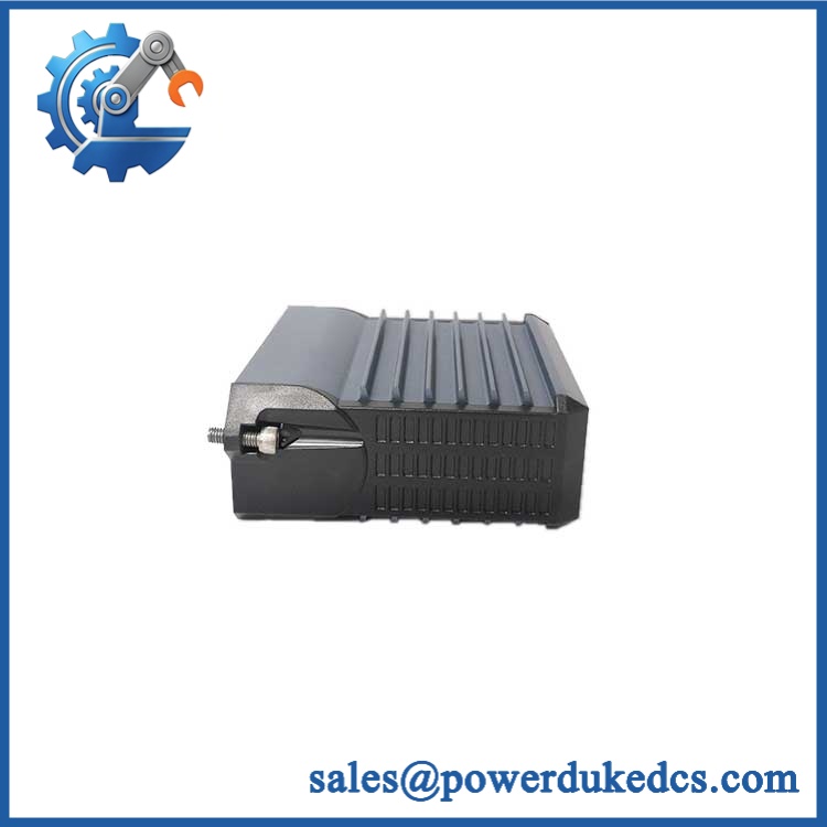
Foxboro E69F-BI2-S
Migration, Compatibility & Installation Traps
Replacement Compatibility Matrix
| Replacement Scenario | Classification | Required Engineering Action |
|---|---|---|
| E69F-BI2-S replaced with an equivalent -BI2-S | Drop-in Replacement — conditional | Match input and output ranges, direct or reverse action, gauge arrangement, mounting, pneumatic ports, electrical connections, and certification. Recalibrate and perform a loop test before returning to service. |
-BI2-S replaced with -BI2 without the -S option |
Hardware Configuration Difference | The standard model does not specify the same integrated pressure-gauge option. Assess local pressure monitoring requirements and the installed piping arrangement before substitution. |
| -S replaced by an IP26-series converter | Engineering-Approved Migration Required | Verify the signal range, pressure supply, output range, mounting footprint, connections, action, and area certification. Assess any mechanical or pneumatic changes before approving the replacement. |
Field Traps to Watch
Supply pressure and instrument-air quality
For the standard 3–15 psi output, the nominal supply pressure is 20 psi. Supply pressure must remain at least 3 psi above the maximum output signal pressure. Air contaminated with water, oil, or particulates can impair the internal pneumatic relay and affect calibration or output response. Verify the regulator setting and air quality before replacing a converter that appears to have an output fault.
Enclosure selection and hazardous-area certification
The -B designation identifies the bolted-cover weatherproof configuration. Weatherproof protection does not, by itself, establish suitability for every hazardous location. Check the nameplate, applicable electrical classification, and installation requirements before installing the instrument in a classified area. The -S suffix specifies integral supply and output pressure gauges, not the miniature junction-box option.
Calibration interaction
For a direct-acting, standard-range unit, the nominal calibration points are 4 mA to 3 psi, 12 mA to 9 psi, and 20 mA to 15 psi. Reverse-acting configurations require the corresponding inverse response. Any span adjustment can affect zero, so recheck both endpoints after calibration rather than accepting a midpoint result alone.