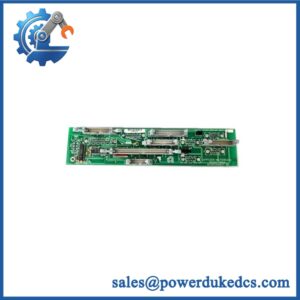
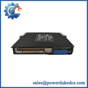
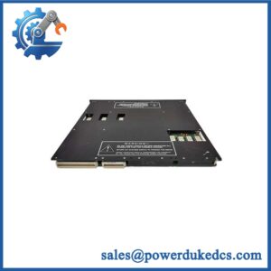
Description
- Brand: TRICONEX
- Full Model Number: 8120X
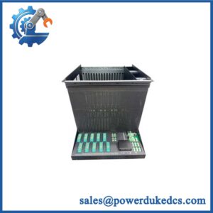
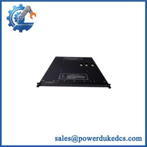
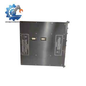
- Product Description: Tricon CX Main Chassis
- Lifecycle Status: Tricon CX product; a 2021 manufacturer environmental profile listed the product as active. Confirm current ordering status and support availability before purchase.
- Core Function: Main chassis and backplane interface for a Tricon CX high-availability safety instrumented system (SIS)
- Top 3 Technical Specs:
- Main Processor Capacity: Three Model 3009X main processors
- Communication Capacity: Four communication modules arranged in two redundant pairs
- Power Supply: External redundant 24 VDC supplies
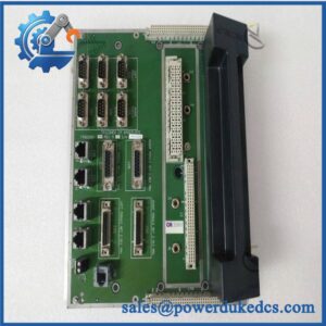
- Expansion Interface: Triplicated RS-485 bidirectional communication ports for connection to the Model 8131X I/O expansion chassis
- Integration: Supports Foxboro DCS time synchronization interfaces
- Compatible Communication Modules: Model 4355X Tricon Communication Module and Model 4610X Unified Communication Module, subject to system configuration
- Mounting: Rack or panel mounting with the applicable mounting brackets
- Stock & Condition: Confirm inventory, hardware identification, included accessories, inspection status, and dispatch date during quotation
Obsolescence & Supply Chain Deep Dive
A failure in the main chassis can affect an entire Tricon CX safety control installation. The TRICONEX 8120X provides the backplane interface for up to three Model 3009X main processors and four communication modules in two redundant pairs. It also connects to the Model 8131X I/O expansion chassis through triplicated RS-485 communication ports. For maintenance teams supporting established safety systems, sourcing the correct chassis can help avoid an unnecessary redesign of processor mounting, communications, and system interfaces. Confirm the complete model designation and existing system configuration before ordering; similarity to another Tricon chassis does not establish compatibility.
The economic case for replacing a failed 8120X depends on the condition of the existing installation and the scope of required validation. Retaining the same chassis model may reduce engineering, cabinet modification, wiring, and commissioning costs compared with migrating to another control platform. The total cost of ownership should include the replacement chassis, inspection, installation labor, restoration of communications, and safety-function verification. An available spare can also shorten procurement exposure when an unplanned shutdown occurs. However, the lowest purchase price is not always the lowest lifecycle cost; the supplied unit must match the installed Tricon CX architecture and meet the maintenance team’s acceptance criteria.
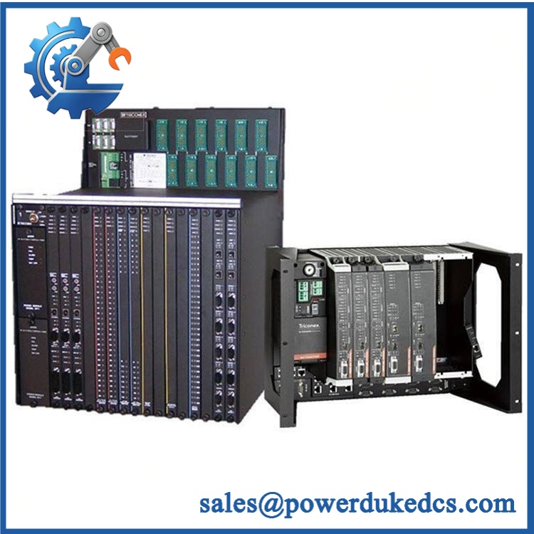
TRICONEX 8120X
Compatibility & Replacement Matrix
The 8120X is the main chassis for the Tricon CX platform, not a general-purpose rack for every Triconex controller generation. Approve a replacement based on platform compatibility, installed modules, communication requirements, and the existing cabinet arrangement.
| Replacement Scenario | Compatibility Classification | Estimated Labor and Planning |
|---|---|---|
| Identical 8120X with matching mounting arrangement and compatible installed modules | Conditional Drop-in Replacement | Approximately 4–8 technician hours for isolation, module transfer, reconnection, and initial testing |
| Identical chassis requiring extensive communication reconnection or cabinet rework | Hardware and Configuration Review Required | Approximately 8–16 technician hours, depending on cable access and documentation quality |
| Different Triconex chassis generation or migration to another safety controller platform | Engineered Migration Required | Approximately 24–80+ engineering and technician hours, depending on application complexity and validation scope |
These are preliminary planning estimates, not manufacturer-prescribed installation times. Actual work depends on site safety procedures, system availability, module configuration, wiring complexity, and commissioning requirements.
Field Traps to Check Before Ordering
Processor and Communication Slot Compatibility
The 8120X is designed for three Model 3009X main processors and up to four communication modules in two redundant pairs. Communication modules must be selected according to the installed network architecture. Confirm whether the system uses Model 4355X communication modules, Model 4610X unified communication modules, or a supported combination. Verify the slot assignments and current configuration records before transferring modules.
Power Supply and Redundant Feed Configuration
The 8120X uses external redundant 24 VDC power supplies. Before installation, verify the supply voltage, polarity, cable terminations, protective devices, and availability of both power feeds. The main chassis includes separate Power 1 and Power 2 status indicators. Inspect the associated power connections and fuse indicators rather than assuming that correct voltage at one feed establishes normal operation of the redundant arrangement.
Expansion Bus and Communication Connections
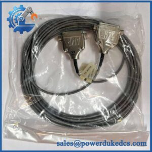
The chassis connects to the 8131X I/O expansion chassis through triplicated RS-485 communication ports. Identify the existing bus connections and check cable assignments, termination requirements, and the installed communication configuration. If Foxboro DCS time synchronization is used, verify the applicable interface requirements and associated hardware before transferring or commissioning the replacement.
Quality Assurance & Testing SOP
The pre-shipment inspection of the TRICONEX 8120X should distinguish physical condition, chassis-level electrical checks, and system-level functional verification. A chassis cannot be fully validated by inspecting its enclosure alone. Testing claims should reflect the actual equipment, modules, and diagnostic setup used.
Visual Inspection and Manufacturer Identification
- Conduct an OEM anti-counterfeit visual inspection of the TRICONEX branding, 8120X model designation, available serial identification, and chassis labels.
- Compare the identification details against the purchase specification and available manufacturer documentation.
- Inspect the backplane interfaces, processor and communication module slots, connectors, mounting brackets, and chassis structure.
- Check for bent contacts, corrosion, contamination, heat discoloration, damaged connectors, or evidence of unauthorized repair.
- Inspect power terminal connections, alarm terminals, and the visible condition of protective components.
- Photograph the identification label, front and rear interfaces, and overall chassis condition.
Power-On and Chassis Status Checks
- Check the external power supply arrangement and verify that the test setup meets the documented 24 VDC input requirements.
- Confirm that the required protective devices and connections are suitable for the test configuration.
- Energize the chassis under an approved controlled test procedure.
- Inspect the Power 1 and Power 2 indicators for the expected response.
- Check chassis alarm and open-fuse indications, where applicable.
- When compatible modules are installed, review their diagnostic status and record unexpected faults.
- Do not treat a successful power-on as proof of complete processor, communication, or safety-system functionality.
Communication and System-Level Functional Testing
- Install compatible Model 3009X processor modules and the applicable communication modules in the approved test configuration.
- Verify that the chassis recognizes the installed hardware and that available diagnostic checks report acceptable status.
- Check communication paths and the configured interface to an 8131X I/O expansion chassis where the test setup supports it.
- Verify communication-module operation against the configured system requirements.
- Exercise the applicable communication interfaces and inspect for communication failures, unexpected alarms, or intermittent faults.
- Check Foxboro DCS time synchronization only when the required interface hardware and test environment are available.
- Record each test performed, its result, and any functions excluded from the test scope.
Final Inspection and Shipment Records
- Record the chassis model, available serial identification, physical condition, inspection date, and test results.
- Document the installed modules used during functional testing, if applicable.
- Identify missing accessories or limitations against the agreed purchase specification.
- Retain the applicable inspection photographs and test report.
- Protect the backplane interfaces and connectors against electrostatic discharge, impact, and contamination during packaging.
Safety-system acceptance requirement: Bench testing does not replace site commissioning. Qualified personnel must validate processor redundancy, communication paths, I/O operation, fault handling, and the affected safety functions under the site’s approved procedures before returning the system to service.
Procurement & Lifecycle FAQ
Is the TRICONEX 8120X in stock, and what is the cutoff for emergency shipping?
Availability depends on the specific inventory allocation and condition. Confirm the 8120X model, quantity, physical condition, included accessories, and required inspection scope when requesting a quotation. Emergency dispatch depends on payment clearance, agreed testing, packing requirements, and the carrier’s collection schedule. Request written confirmation of the dispatch date when the chassis is needed for a critical shutdown.
How do you verify the authenticity and condition of TRICONEX 8120X chassis units?
The inspection process should include model and identification checks, examination of the backplane and connectors, and review of visible signs of damage or unauthorized repair. Where testing facilities are available, chassis-level electrical checks and compatible system-level diagnostics provide further evidence. Request current unit photographs and the applicable inspection report before releasing the purchase order. Visual inspection alone cannot establish full system functionality or product provenance.
Are there processor or firmware compatibility issues to review before issuing the purchase order?
Yes. Confirm compatibility with the installed Model 3009X main processors, communication modules, Tricon CX configuration, and relevant software or firmware revisions. Review slot assignments and communication settings before moving existing modules. Do not assume that matching chassis dimensions or a similar model designation establishes compatibility with another Triconex platform.
What warranty and return terms apply to the TRICONEX 8120X?
Warranty coverage and return eligibility should be documented in the quotation or pro forma invoice before purchase. Confirm the warranty period, covered defects, exclusions, claim procedure, and return authorization requirements. Verify whether the unit is new, surplus, or previously used, and request written confirmation of the condition and testing scope. Do not assume identical coverage for every stock condition.
Should we replace the 8120X or migrate to a newer safety controller?
A matching replacement can be the lower-cost option when the existing Tricon CX installation remains suitable and compatible hardware is available. Migration may be justified when spare availability is uncertain, lifecycle support no longer meets site requirements, or the control system needs additional capabilities. Compare equipment cost, engineering effort, application conversion, cabinet changes, testing, and planned downtime. Any migration affecting safety-related functions requires a documented engineering assessment and formal validation before operation.