Description
- Brand: FOXBORO
- Full Model Number: CMP10
- Associated Part Number: P0400VP
- System/Series Family: Foxboro I/A Series Distributed Control System
- Core Function: Communication processor module for industrial control-system communication and data exchange.
- Top 3 Technical Specifications:
- Module Type: CMP10 communications processor
- Part Identification: P0400VP
- System Integration: Foxboro I/A Series architecture; compatibility depends on the installed system configuration
- Stock Status: Current availability, physical condition, and warranty terms subject to the actual inventory lot and quotation.
Technical Product Introduction
Communication processor failures in a legacy Foxboro I/A Series installation can disrupt data exchange across the control architecture, complicating troubleshooting and extending maintenance outages. The FOXBORO CMP10, associated with part number P0400VP, is a communications processor used within the I/A Series platform. For maintenance teams supporting an established process-control system, identifying the correct processor is essential before removing hardware or changing network connections. A matching model designation alone is not sufficient; confirm the complete part number, hardware revision, and installation requirements against the equipment already in service.
The primary replacement benefit is the ability to source the intended processor without automatically undertaking a wider control-system migration. Where the existing hardware and software configuration support the replacement, retaining the established architecture can reduce engineering rework, commissioning time, and procurement costs. Exact processor speed, memory capacity, firmware requirements, and communication-interface specifications should be taken from applicable Foxboro technical documentation rather than inferred from the model designation. Compared with replacing an entire control subsystem, a correctly matched CMP10 can provide a more focused maintenance option, provided the original fault has been isolated to this component and the surrounding hardware remains serviceable.
Application Scenarios & Field Realities
- Legacy process-control systems: When a communications fault affects an established Foxboro I/A Series installation, verify the CMP10 identification and its position within the control architecture before replacing the module. A failed processor is only one possible cause; inspect associated connections and system diagnostics as well.
- Refinery and petrochemical operations: During a planned maintenance outage, a verified replacement processor can help limit the scope of hardware intervention. Preserve the approved configuration and document existing connections before removal, particularly when multiple control nodes depend on the affected communication path.
- Power generation and utility control: Where operating personnel rely on established control-system data exchange, replacement planning should include a review of alarms, communications status, and dependent control functions. Perform the change under the site’s approved maintenance procedure rather than assuming that successful module startup guarantees full system recovery.
- Lifecycle support for older installations: When the original processor becomes difficult to source, compare the available CMP10 hardware against the installed part number and revision. Purchasing a nominally related processor without checking its system role can introduce an avoidable compatibility problem.
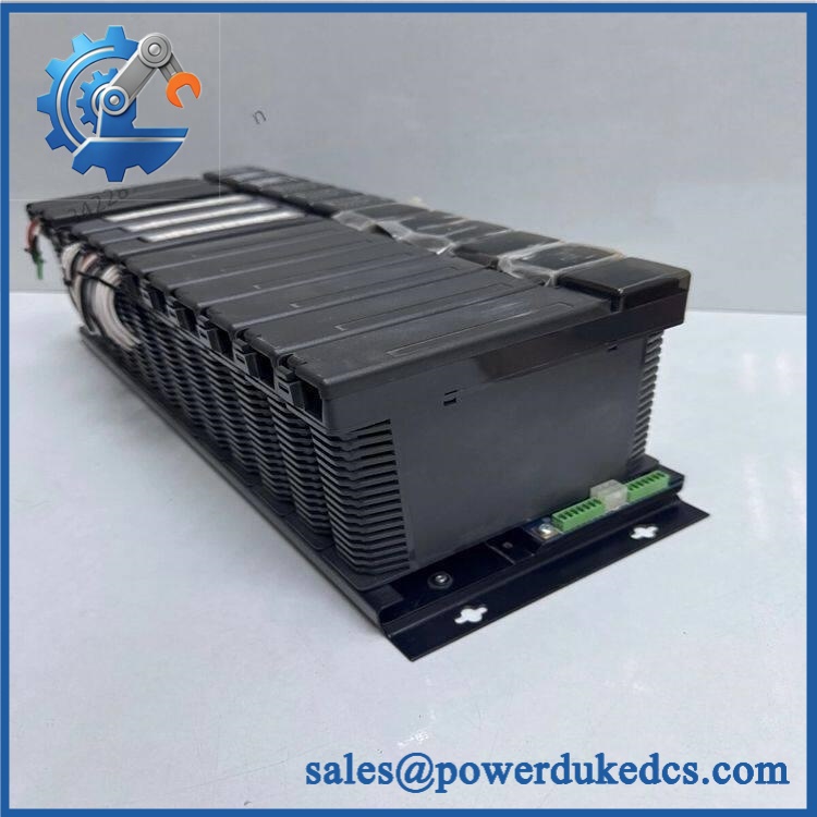
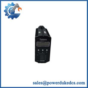
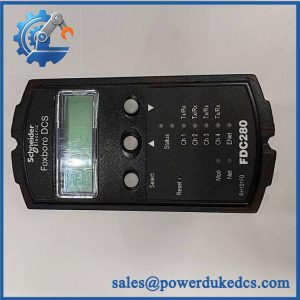
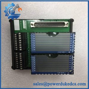
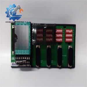
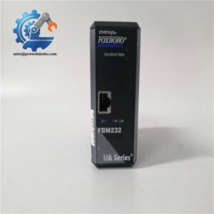
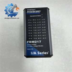
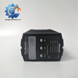
Foxboro CMP10 P0400VP
Migration, Compatibility & Installation Traps
Replacement Compatibility Matrix
| Classification | Engineering Assessment |
|---|---|
| Drop-in Replacement | Conditional. A carrying the matching P0400VP part identification is a candidate replacement, subject to hardware revision, mounting/interface requirements, and system compatibility checks. |
| Software Compatible | Configuration-dependent. Verify the supported processor revision, installed software release, and applicable configuration requirements. Do not assume a firmware update or recompilation is either necessary or sufficient. |
| Hardware Modification Required | Not normally expected for a correctly matched assembly. A different processor variant, interface arrangement, or mounting configuration may require additional engineering work and approval. |
Field Traps to Watch Out For
Processor variant confusion
The communications processor should not be confused with other Foxboro processor types simply because they belong to the same I/A Series family. Confirm the complete module designation and part number against the existing unit and approved equipment records. Do not substitute a related processor based only on appearance or physical fit.
Configuration and communication faults
Before removing the existing module, document available diagnostic information and preserve applicable configuration records. Following installation, check the module’s status indicators according to its faceplate legend and the relevant hardware manual. Verify communication with the intended system components before declaring the replacement successful.
Controlled installation and restart
Follow the approved isolation, electrostatic-discharge protection, insertion, and startup procedures for the installed hardware. Do not assume hot-swapping is supported. After replacement, confirm the applicable communication status, review system diagnostics, and verify the operation of dependent control functions.
Quality Assurance SOP
Pre-shipment inspection for FOXBORO should establish the identity and physical condition of the specific unit being supplied. Functional testing should be performed using appropriate equipment and a compatible test environment. Any limitations should be documented rather than represented as completed tests.
Visual Inspection and Part Identification
- OEM Identification Inspection: Examine the Foxboro branding, model designation, P0400VP part identification, serial number where available, and hardware revision markings. Compare these details with accepted documentation or reference hardware. Visual checks alone cannot establish OEM authenticity.
- Physical Condition Inspection: Check the enclosure, board edges, connectors, contact surfaces, and mounting features for corrosion, contamination, impact damage, or evidence of unauthorized repair.
- Connector and Interface Inspection: Examine accessible communication interfaces and electrical contacts for deformation or contamination. Confirm that the physical configuration matches the intended application.
- Inventory Documentation: Record the observed part identification, available revision details, visible condition, and photographs of the actual unit.
Electrical and Functional Testing
- Power-On Self-Test (POST): Where a compatible test setup is available, apply the correct supply arrangement and observe startup behavior. Record the applicable status LED indications and diagnostic results against the hardware documentation.
- Hardware Recognition Test: Install the module in an approved compatible test environment and confirm that the host system recognizes the expected processor identification and reports no unexplained hardware faults.
- Communication Handshake Verification: Verify communication with the appropriate system interface or test endpoint. Record the test arrangement and confirm that expected communication responses are received.
- Diagnostic Review: Examine available module and host-system diagnostics for startup failures, communication alarms, or unexpected status indications.
- Stability Test: Where supported by the available test environment, operate the module for an agreed observation period and monitor for resets, intermittent communication, or recurring diagnostic errors.
Pre-Shipment Release Criteria
Release the only after the inspection findings and completed test results have been reviewed against the agreed acceptance criteria. The inspection record should identify the unit, describe its supplied condition, document the functional tests performed, and state any limitations.
Final acceptance: A successful standalone test does not establish full compatibility with every Foxboro I/A Series installation. Before returning the process to service, verify the installed software configuration, communication path, system diagnostics, and required control functions under the site’s approved commissioning procedure.