Description
- Brand: Foxboro
- Full Model Number: CP40B
- System/Series Family: I/A Series Hardware; Control Processor 40, Style B
- Core Function: Regulatory control, logic execution, timing, sequential control, fieldbus data acquisition, and alarm processing
- Top 3 Technical Specs: AMD 486DX5 processor at 133 MHz; 4 MB storage; EIA RS-485 Fieldbus at 268.75 kbps
- Fieldbus Capacity: Up to 24 Fieldbus Modules on the local bus; up to 64 on an extended bus, excluding expansion modules
- Redundancy: Optional fault-tolerant configuration using two CP40B modules and an interconnecting ZA-bus
- Operating Environment: 0 to 60°C; 5–95% relative humidity, noncondensing
- Stock Status: Unit-specific availability and condition verified at order time; condition stated on the quotation
- Pre-Shipment Documentation: Model and label inspection, physical condition report, applicable functional test results, and warranty terms
The technical specifications above are drawn from the Foxboro I/A Series Control Processor 40, Style B product specification, PSS 21H-1B5.
Technical Product Introduction
A failed controller can interrupt regulatory loops, sequential logic, fieldbus communications, and alarm processing across a legacy distributed control system. The Foxboro CP40B Control Processor 40, Style B serves as a central processing module in Foxboro I/A Series architectures. It executes control strategies, acquires process data through Fieldbus Modules (FBMs), and supports alarm detection and notification. For maintenance teams managing installed I/A Series equipment, this model offers a route to restoring the existing control architecture without automatically redesigning the entire node. Hardware identity, software configuration, and the installed fieldbus topology must still be checked before replacement.
On the engineering side, the CP40B uses an AMD 486DX5 microprocessor running at 133 MHz and provides 4 MB of storage. Fieldbus communications operate at 268.75 kbps, with supported configurations including local EIA RS-485 connections up to 10 m, extended twinaxial connections up to 1,800 m, and fiber-optic extensions up to 20 km when the appropriate interface equipment is installed. These are architecture limits, not a guarantee of application response time. Actual control performance depends on the configured strategy, block execution requirements, communication loading, and the condition of the existing hardware. Compared with earlier control-processor configurations, migration to the CP40B may require station-definition and software-license changes rather than a simple physical swap.
Application Scenarios & Field Realities
- Refinery process control: In distillation, hydroprocessing, and product-transfer units, the controller may execute regulatory loops alongside interlocks and sequential logic. Before replacing a CP40B, verify which control compounds and I/O dependencies reside on the affected node. A successful processor startup alone does not prove that all operating loops have been restored.
- Power generation and utility auxiliaries: Boiler auxiliaries, cooling-water systems, and balance-of-plant equipment may depend on established timing logic, operator indications, and alarm handling. Where a redundant controller pair is installed, confirm that both processors and their communication paths are configured correctly before returning the node to service.
- Batch chemical production: Timed sequences, valve operations, permissive checks, and analog feedback often share a controller’s processing resources. Review sequence definitions and control-block assignments after a replacement. The downloaded configuration must match the intended process state; otherwise, a healthy processor can still operate with an incomplete or incorrect control strategy.
- Legacy installations with distributed I/O: For production assets using remote FBMs, SPEC 200 migration equipment, or SPECTRUM migration interfaces, fieldbus hardware matters as much as the CPU. Twinaxial extension requires the appropriate isolator arrangements, while fiber-optic configurations require compatible optical interface equipment. Confirm the installed architecture before selecting a replacement or planning a controller upgrade.
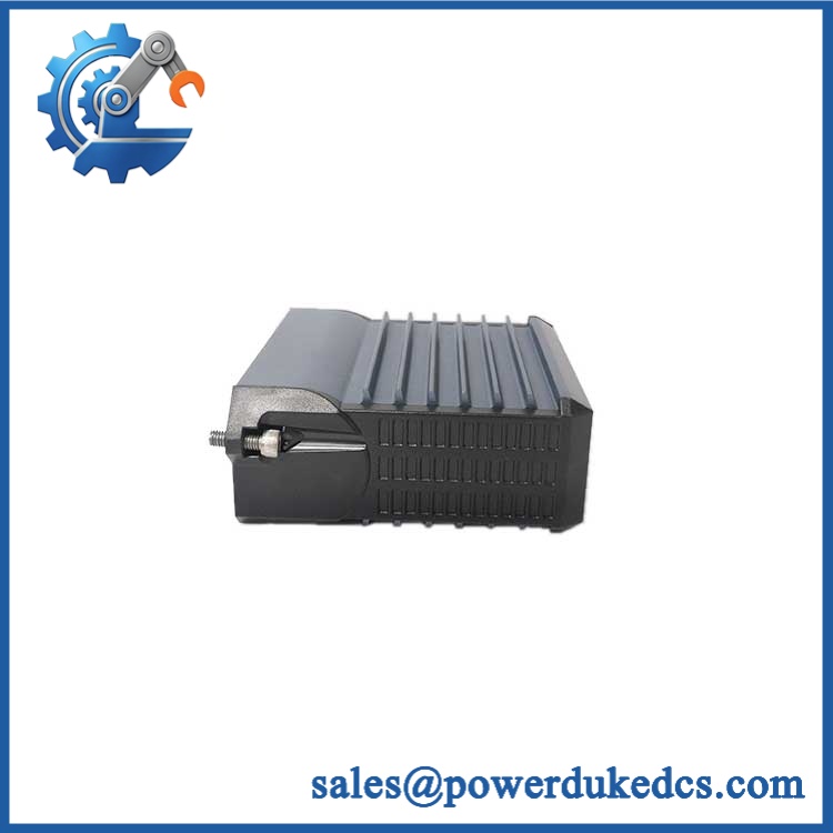
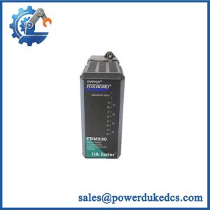
Foxboro CP40B
Migration, Compatibility & Installation Traps
Replacement Compatibility Matrix
| Replacement Situation | Classification | Required Engineering Action |
|---|---|---|
| Existing replaced with a verified equivalent | Drop-in Replacement — conditional | Confirm exact model, part number, hardware revision, firmware/software compatibility, node configuration, and redundancy arrangement. Restore or verify the correct control configuration before service. |
| CP30 or another supported legacy processor upgraded to | Software Compatible — engineering changes required | Review the System Definition Utility configuration, identify the station as , verify software licensing, install the applicable software, and load the correct compounds. This is not automatically a firmware-only upgrade. |
| Conversion from simplex operation to a fault-tolerant pair | Hardware Modification Required — where existing hardware is insufficient | Provide two modules in adjacent mounting slots and the required interconnecting ZA-bus; verify the redundant Nodebus and Fieldbus configuration. |
Replacement decision: A same-model replacement is the lowest-risk option, but physical fit does not establish complete compatibility. The applicable I/A Series software level and the existing control-node configuration remain decisive. Foxboro’s upgrade instructions specifically describe station-definition, software-license, software-installation, and compound-loading steps for applicable processor upgrades.
Field Traps to Check Before Installation
Fieldbus topology and termination
The supports different fieldbus arrangements, each with specific interface and distance requirements. The local bus supports up to 24 FBMs over a maximum stated length of 10 m. Extended twinaxial installations support up to 64 FBMs, excluding expansion modules, with a maximum length of 1,800 m and the required isolators. Fiber-optic extensions can reach 20 km with compatible optical equipment. Confirm cable type, isolator or modem selection, bus termination, and installed module count before commissioning.
Redundant mounting and ZA-bus
For fault-tolerant operation, two modules must occupy adjacent mounting slots and use the required ZA-bus interconnection. Installing a single processor in a redundant node does not restore the complete redundant arrangement. During maintenance, also follow the site’s isolation and electrostatic-discharge procedures; the presence of a front-panel reset button is not a substitute for an approved service procedure.
Quality Assurance SOP
The following pre-shipment inspection sequence defines the checks to document for each supplied . Results should be recorded against the individual unit, not inferred from a model number or product photograph.
Incoming Inspection and Verification
- OEM anti-counterfeit visual inspection: Examine manufacturer markings, model identification, serial or tracking labels where present, connector condition, enclosure, and accessible board details. Compare these with available manufacturer references. Record discrepancies and quarantine units with unexplained inconsistencies.
- Physical condition inspection: Check for damaged connectors, bent contacts, corrosion, contamination, cracked components, evidence of unauthorized modification, and shipping damage.
- Identity and configuration record: Record the model, available part-number and revision information, serial or tracking reference, and the supplied condition classification. Photograph the unit before packing.
Power-On and Functional Checks
- Power-on self-test (POST): Where a compatible test setup is available, power the module using the specified hardware configuration. Observe the red and green status LEDs throughout startup and record the actual indications. Do not substitute assumed RUN/ERR labels for the indicators fitted to the particular revision.
- Power supply verification: Check the supply arrangement against the applicable hardware documentation. The specification states 39 V DC as the typical input voltage for the redundant-voltage arrangement; verify the exact setup before applying power.
- Communication handshake verification: Where suitable equipment is available, check communication with a compatible I/A Series test node over the applicable Nodebus and Fieldbus interfaces. Record link status, detected faults, and any communication failures.
- Diagnostic review: Review available startup self-checks, runtime monitoring, watchdog indications, and supported offline diagnostics. Record each test as passed, failed, or not performed, with a reason for any omitted test.
- Redundancy verification: For units supplied for a fault-tolerant configuration, check the applicable paired-module arrangement, ZA-bus connection, and communication paths using compatible test equipment.
Final Release and Packing
- Test report: Retain the unit identity, inspection findings, functional test results, test date, and any limitations of the test setup.
- Condition declaration: State whether the supplied unit is new surplus, factory sealed where applicable, or tested used. Do not describe a unit as fully tested unless the documented checks support that claim.
- Warranty documentation: Confirm the actual warranty period and exclusions in the quotation or sales documents before dispatch.
- ESD-safe packing: Protect connectors and the module against electrostatic discharge, mechanical impact, and moisture during transit.
Acceptance criterion: Release the only when its identity and physical condition have been documented, the applicable agreed functional checks have passed, and any limitations are disclosed. A successful bench test does not replace verification of the customer’s installed I/A Series configuration or prove that the complete process-control system is operational.