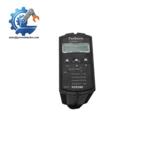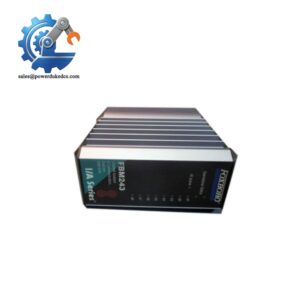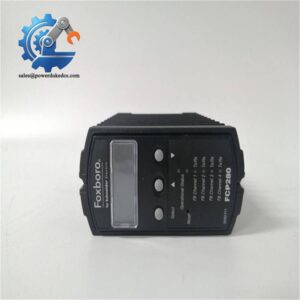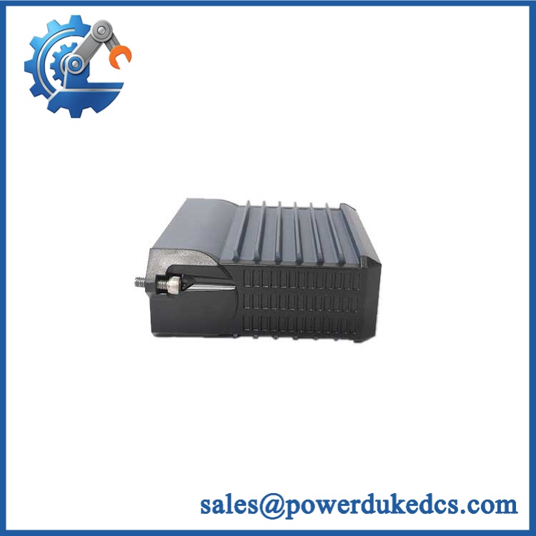
Description
-
Brand: Foxboro by Schneider Electric
- Full Model Number: FBM230
- OEM Part Number: P0926GU
- System / Series Family: Foxboro I/A Series DCS and supported Foxboro DCS 200 Series configurations
- Core Function: Four-port Field Device System Integrator module connecting third-party serial devices to a Foxboro distributed control system.
- Top 3 Technical Specs: Four independently configurable serial ports; RS-232, RS-422, or RS-485 per port; redundant 24 VDC supply input rated +5% / -10%.
- Maximum Power Consumption: 7 W
- Maximum Device Capacity: Up to 64 RS-485 devices across four ports, subject to protocol and performance limitations
- Data Integration Capacity: Up to 2,000 Distributed Control Interface (DCI) connections
- Communication Cycle: Fastest permitted ECB block period of 500 ms
- Module Fieldbus: Redundant 2 Mbps communication paths
- Lifecycle Status: Current OEM product documentation is available; exact manufacturing status and order availability require confirmation.
- Stock Status: Quantity, condition, revision, and functional-test records require confirmation before ordering.
Commercial-Technical Deep Dive
A serial communication failure can isolate critical instruments from the DCS without affecting the instruments themselves. The Foxboro FBM230 P0926GU provides a four-port Field Device System Integrator interface for connecting third-party equipment to the Foxboro control database. Each port supports independent software configuration for RS-232, RS-422, or RS-485. That flexibility matters when a control cabinet contains devices with different electrical interfaces or serial communication settings. Depending on the installed protocol driver, the module can read or write process values and status data, with support for up to 2,000 DCI connections. Actual device capacity and update performance depend on the protocol, data layout, controller capacity, and configured scan requirements.
At a maximum consumption of 7 W, the FBM230 can preserve an established serial integration architecture without introducing a separate gateway for every field device. Four RS-485 buses can support up to 64 devices in total, with up to 16 devices per port under the documented configuration limits. RS-232 links are intended for direct connections, while RS-422 and RS-485 support longer cable runs; the documented maximum is 15 m for applicable RS-232 custom cables and up to 1,200 m for RS-422 or RS-485. The module also communicates through redundant 2 Mbps fieldbus paths. For an existing installation, retaining the approved driver, serial settings, and DCI mapping can reduce engineering effort and help avoid unnecessary changes to the control database (actual savings depend on the installed controller and field-device configuration). Before purchasing, verify the exact part number, termination assembly, and system compatibility.
Compatibility & Installation Traps
Migration and Compatibility
| Replacement Scenario | Classification | Required Action |
|---|---|---|
| Existing FBM230 P0926GU replaced with the same approved model | Conditional drop-in replacement | Match the part number, hardware revision, baseplate, termination assembly, and supported controller configuration. |
| Same hardware with an existing protocol driver and configuration | Configuration retention may be possible | Confirm driver availability, port parameters, device addressing, and DCI mapping before installation. |
| Different FBM230 hardware revision | Engineering verification required | Check revision-specific operating limits and compatibility with the installed Foxboro subsystem. |
| Different serial interface module proposed as a substitute | Not an automatic replacement | Verify port count, electrical interface, protocol support, controller compatibility, and data mapping. |
| Replacement involving a new field-device protocol | Software configuration changes may be required | Confirm the available driver and assess the required DCI configuration and commissioning work. |
Hot-swap and power-down requirements: Foxboro documentation states that the FBM230 can be removed or replaced without disconnecting field-device termination cabling, power cables, or communications cables. However, that statement alone should not be treated as authorization for energized removal in every installation. Follow the approved subsystem maintenance procedure and verify whether live replacement is permitted in the specific configuration. If the procedure does not authorize a hot swap, place affected equipment in the required safe state and follow the prescribed shutdown sequence.
No firmware flash should be assumed necessary for an exact replacement. The downloadable protocol driver and the configured serial parameters are separate compatibility considerations and must be checked against the installed system.
Field Traps to Check Before Ordering
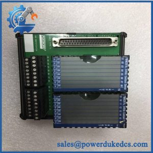
- Termination assembly mismatch: The uses a termination assembly with connection options for RS-232, RS-422, and RS-485. Documented options include the P0926PA ring-lug assembly and the RH926GH compression-screw assembly, which supersedes P0926GH. Confirm the installed assembly and required cable before ordering.
- Serial wiring and termination: RS-485 and RS-422 use configurable termination arrangements, while the RS-232 termination assembly includes DB-25 connectors and signal-selection DIP switches. Incorrect termination, polarity, or signal assignment can prevent communication even when the module powers on normally.
- Driver compatibility: protocol drivers are loaded according to the connected field device. Confirm that the required driver and communication settings are available for the installed Foxboro software environment.
- Electrical isolation limits: The documented 600 VAC withstand rating applies to a specified one-minute isolation test. It does not authorize permanent connection to hazardous-voltage circuits. Observe the published terminal limits and applicable electrical safety requirements.
-
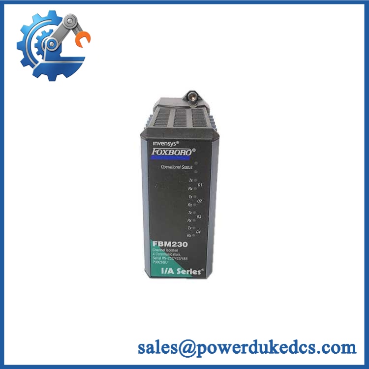
- Foxboro P0926GU
Quality Assurance SOP
The following procedure defines the proposed pre-shipment inspection and testing scope for Foxboro P0926GU inventory. Tests must use the appropriate equipment and follow the applicable product documentation. Any test not performed should be disclosed rather than represented as completed.
Visual Inspection and Product Authentication
- OEM anti-counterfeit visual inspection: Examine manufacturer markings, identification labels, part numbers, serial or production details, and available traceability records.
- Part-number verification: Confirm and P0926GU against the purchase order and photograph the actual module label.
- Physical examination: Inspect the enclosure, connectors, mounting features, and accessible components for corrosion, contamination, impact damage, or evidence of unauthorized rework.
- Revision recording: Record the hardware revision and confirm that its operating-temperature range is appropriate for the installation.
- Condition assessment: Declare the actual condition as new original, new surplus, or previously used, as applicable.
- Termination assembly verification: Check any included termination assembly and cable against the customer’s configuration. Do not assume these accessories are included with the module.
Power-On and Diagnostic Testing
- Verify the compatible baseplate and 24 VDC supply arrangement before energization.
- Confirm that the applied supply remains within the specified +5% / -10% input range.
- Perform a controlled power-on self-test (POST) using an approved test setup.
- Check the module status indicators and the four ports’ transmit/receive activity indicators. Record ERR/RUN indications where those labels are present on the specific hardware revision.
- Confirm that the host controller recognizes the module and that no unexplained diagnostic fault remains.
- Record input voltage, module status, test equipment, and observed results.
CRO-Driven Buyer FAQ
Is the Foxboro obsolete, and can genuine stock still be sourced?
The current OEM product specification provides technical information for the , but it does not independently confirm the manufacturing status or stock availability of every part number and revision. Request written confirmation of the exact part number, quantity, condition, revision, and dispatch date. For new surplus or previously used stock, ask for actual-unit photographs, available traceability records, and a clear condition declaration.
Can the be replaced while the DCS is running?
Do not assume that energized replacement is authorized simply because the module can be removed without disconnecting its field-device termination, power, and communication cables. Check the applicable Foxboro subsystem manual and the site’s approved maintenance procedure. Assess the loss of serial data, affected control functions, and required operating precautions before removing the module. If live replacement is not explicitly approved for the installed configuration, follow the prescribed shutdown and isolation procedure.
Does replacing the require a firmware flash or logic rewrite?
An exact replacement does not automatically require a firmware flash or control-logic rewrite. The critical checks are the supported module revision, the installed protocol driver, serial communication parameters, and DCI mapping. If the replacement changes the protocol, port arrangement, or driver configuration, additional engineering and commissioning may be necessary.
What warranty and technical support terms apply?
Confirm the warranty duration, commencement date, defect coverage, return authorization procedure, and exclusions in writing before placing the order. Establish whether technical support covers hardware testing only or includes assistance with driver selection, serial communication diagnostics, and DCS configuration. Do not assume that a surplus module includes the original manufacturer’s warranty or unrestricted application-engineering support.
What must I verify before ordering the termination assembly and cable?
First, identify whether the installed termination assembly uses ring-lug or compression-screw connections. Confirm the required assembly reference, interconnect cable, serial interface, connector pinout, and termination settings. For RS-485 applications, check bus topology, polarity, termination resistors, and device count. A matching module cannot compensate for an incompatible termination assembly or incorrect serial wiring.